Care and maintenance, Carburetor adjustments, Important – Bolens 520 User Manual
Page 10: Impeller clutch adjustment, Paddle replacement, Note
Attention! The text in this document has been recognized automatically. To view the original document, you can use the "Original mode".
CARE AND MAINTENANCE
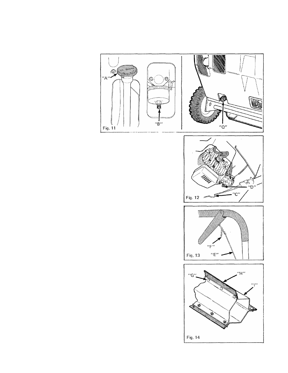
operating position (wheels and
scraper blade on the ground). Clean
dirt and/or snow from around open
ing (A), Figure 11. Keep oil level to
"FULL" mark on dipstick. Refer to
Engine Manual for proper proce
dure to drain and refill engine
crankcase. The drain plug (Q), Fig
ure 11 is located on backside of unit
in the bottom left-hand corner.
Refer to Engine Manual and/or
BEFORE OPERATION instructions
for proper type oil and quantity.
CARBURETOR ADJUSTMENTS
DO NOT MAKE UNNECESSARY
ADJUSTMENTS. FACTORY SET
TINGS ARE SATISFACTORY FOR
MOST APPLICATIONS AND CON
DITIONS. HOWEVER IF ADJUST
MENTS ARE NEEDED, PROCEED
AS FOLLOWS.
4 CYCLE ENGINE - The engine has
been pre-set to run at 3600 RPM.
Turn high speed adjustment needle
(B), Figure 11, to regulate flow of
gasoline to the engine. For com
plete adjustment procedure, refer to
Engine Manual.
IMPORTANT
When closing adjusting needles,
close finger tight only. Forcing may
cause damage.
2 CYCLE ENGINE
- The engine has
been pre-set to run at 4300 RPM.
Through opening (C), Figure 12, in
hand side of machine, turn the
mixture adjusting screw (D) (using
a screwdriver) to regulate flow of
f u e l t o
the engine.
IMPORTANT
Do not force screw tight. Damage to
carburetor or screw could occur.
Refer to Engine Manual for com
plete adjustment procédure.
IMPELLER CLUTCH ADJUSTMENT
(for models so equipped)
Adjust cable (E), Figure 13 up or
down by moving chain (F) one-half
line (one loop) at a time. If impeller
doesn’t rotate when engaged,
unhook chain, pull up on cable and
rehook chain in next lower loop. If
impeller rotates without engaging,
unhook chain and rehook chain in
10
next highest loop. Repeat proce
dure until proper adjustment is
achieved.
PADDLE REPLACEMENT
If paddles become worn and fail to
propel the snow thrower, replace
ment may be necessary. Replace all
3 paddles, one at a time. STOP
ENGINE.
1. Remove screws (G), Figure 14,
that secure paddle (H) to Impeller
frame (I).
2. Remove old paddle.
3. Install new paddle and secure it
to impeller using the same screws
and hex nuts used to secure old
paddle.
4. Repeat procedure for other
paddles.
BELT ADJUSTMENT - MODELS
225, 225E, 300 & 300E
If the Idler pulley does not apply
enough tension to belt to drive
impeller, adjust belt as follows:
1. Remove drive cover. Remove
the (8) screws (A & B) shown in
Figure 16. Two plugs, in cover, must
be removed to reach screws (A).
2. Remove anchor screw (Q), Fig
ure 15, and reinstall screw in low
position shown in Figure 15.
NOTE
Spring must never be stretched
(measured from end to end) more
that 3" (76 mm), if necessary, repo
sition anchor screw to position "X",
Figure 15.
3. Reinstall drive cover.