Furnace circuits, Blower motors, Fan control switch – Bard 2100-066 Rev. A User Manual
Page 6: Furnace circuits blower motors fan control switch, Electrical system components
Attention! The text in this document has been recognized automatically. To view the original document, you can use the "Original mode".
Electrical System Components
Furnace Circuits
All circuits within the oil firmaces are designed and wired in
accordance with Underwriters Laboratories’ requirements. They
have been inspected and tested at the factory to qualify for the UL
label which is attached to the furnace.
All circuits within the gas firmace are designed and wired in
accordance with American Gas Association requirements. They
have been inspected and tested at the factory to qualify for the
AGA Label which is attached to the furnace.
Black
White
Fused switch box
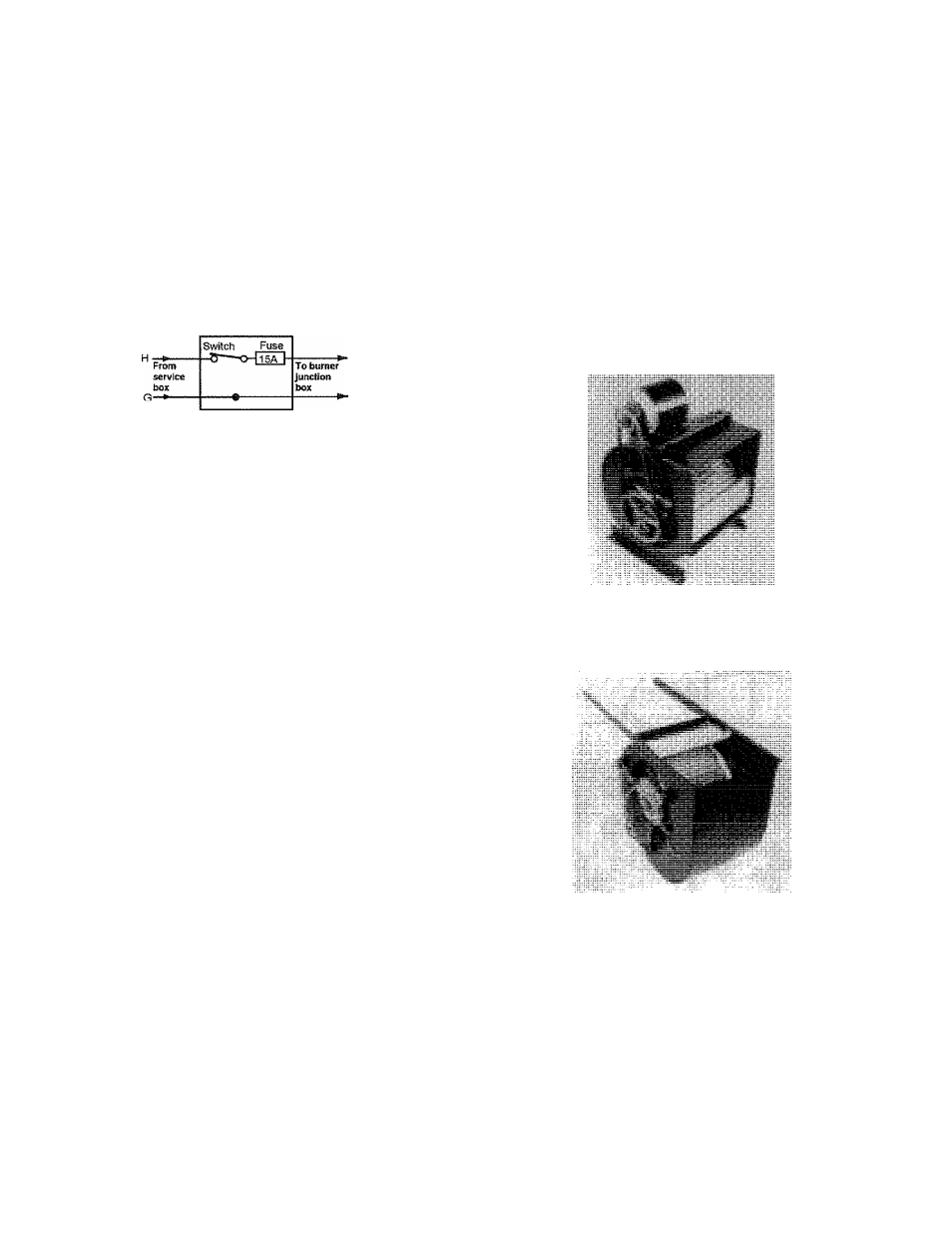
All switching within the furnace line voltage circuits is done in the
hot 120V leg. The reason is that switching, if done in the ground
leg, could result in an unsafe grounding fault. See diagram.
Switch open, furnace
does not run, fuse blows_
when switch closes
Short to
ground
X
Gi|(-
To
furnace.
Switch in hot leg
Right
Wrong
Switch in ground leg
G.||-
Switch open
furnace runs
fuse does not blow
To
furnace
ground
The first load in all forced warm air systems is the blower motor
which is always line voltage. Therefore, the fiimace blower motor
is the first electrical component wired into the system.
Now when the disconnect switch lever is closed to the “on”
position, this will make a complete circuit and energize the
blower motor. This motor, in turn, drives the blower which
delivers the air through the furnace and duct system. When
the lever is placed in the “off” position, the circuit is not complete
and the blower motor will not run. Airflow in the system will stop.
The fuse in the switch is placed there to monitor the amount of
current flow in the circuit. If there should be excessive current
flowing in the circuit, the fuse will bum out and open the circuit.
Blower Motors
At this point, the blower motor has been wired into the circuit. This
is the basic circuit shown in the wiring diagrams. However, there
are variations in the blower motors used and the way they are
connected electrically. These variations and the reasons for each are
discussed in Manual 2100-058, “Basic Electricity.”
The type and size of blower motor installed in a fiimace depends
upon flie blower load required to deliver the correct amount of air to
the heating system. Because the heating system varies from one
installation to another, the blower speed needs to be adjustable to
match the needs of the air distribution system. This speed
adjustment may be done either mechanically or electrically.
The motor may be connected to the blower by a belt and pulley. In
this case, the speed adjustment is accomplished mechanically by a
change in the pulleys. This is referred to as a “belt-drive blower.”
Or the blower wheel may be mounted directly on the motor shaft.
In this case, the motor speed must be changed electrically. This is
referred to as a “direct-drive blower,”
Fan Control Switch
One of the major controls in the line voltage circuit will be the fan
control. The fan control switch is a heat-actuated switch which is
equipped with normally open contacts. It contains a bi-metal type
of heat sensing probe which senses the temperature of the air
passing from the furnace into the system.
The furnace illustration shows the location of the fan control in an
upflow type fiimace. The probe is usually a “spiral” type and is
installed into the heating unit on the front side of the cabinet with
the bimetal probe inserted through the cabinet into the heat
exchanger portion of the furnace. Its position must be such that the
bimetal probe can sense the temperature of the air passing from the