Optional “auto-fill, Description, Getting started – CMA Dishmachines CMA-66 User Manual
Page 12
Getting Started
2.2.8. Optional
“Auto-Fill”
With this function a single press of the AUTO FILL switch fills the machine to the
proper level.
If your Dishmachine did not come with the Auto-Fill option already installed, an
Auto-Fill kit is available. Call (800) 854-6417 and order Kit #13468.00
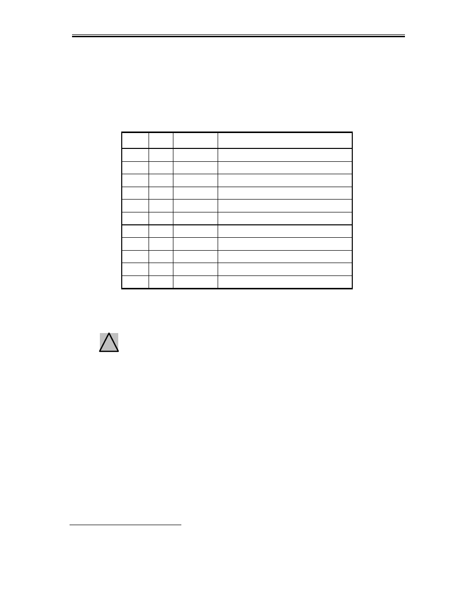
Kit #13468.00 Includes:
ITEM QTY
P/N
DESCRIPTION
1
1
00421.89 Rocker Switch, Momentary
2 1
13418.85
Timer
Relay
3*
1
13419.85 Timer Relay Socket
4
1
13003.61 DIN Rail, 3” (with 2-sided tape)
5 1
00705.05
Solenoid
Valve
6
1
00400.10 1/2" Conduit, 2 feet
7
2
00401.10 1/2" Straight Connector
8
2
00907.00 6-32 x 1/2" Pan Head Screw
9
2
00965.00 6-32 Nylon Lock Nut
10 2
00661.00
Wire
Nut
11
2
52000.00 #250 Piggyback Connector
*Item 3: Socket is pre-wired for easy installation
To Install:
1. Disconnect the machine from power at the circuit breaker.
Warning! Turning the machine off at its power switch is not sufficient, as a
shock hazard is still present. Power must be disconnected at the circuit
breaker.
!
1. With the water supply turned off at the source remove the manual fill valve and replace it
with the Solenoid Valve
*,
(P/N 00705.05).
2. Depending on which control cabinet came installed on your machine, there will either be
an area of open DIN rail for mounting the pre-wired Timer Relay Socket (P/N 13419.85)
or there will be two predrilled holes in the upper-right corner. If there is no open area on
the DIN rail but the two holes are present, mount the DIN Rail (P/N 13003.61) inside the
control cabinet using the two 6-32 x 1/2" Pan Head Screws (P/N 00907.00) and 6-32
Nylon Lock Nuts (P/N 00965.00). The screws should be inserted through the DIN Rail
and out the back of the control cabinet.
3. Secure the pre-wired Timer Relay Socket (P/N 13419.85) to the DIN Rail by snapping it
into place. See Figure 1 on the following page for orientation of socket.
4. Remove the blue wire from the Main Contactor coil terminal (see Figure 2 on the
following page) and put one of the two #250 Piggyback Connectors (P/N 52000.00) on
the coil terminal.
**
Electrical and plumbing connections must be made by a qualified person who will comply with all
available Federal, State, and Local Health, Electrical, Plumbing and Safety codes
MODEL CMA-66 Installation & Operation Manual Rev. 1.06 01/11/05
Page
11