Jumper pin & antenna diagrams, Antenna / receiver guide – Crimestopper Security Products EZ-30 User Manual
Page 19
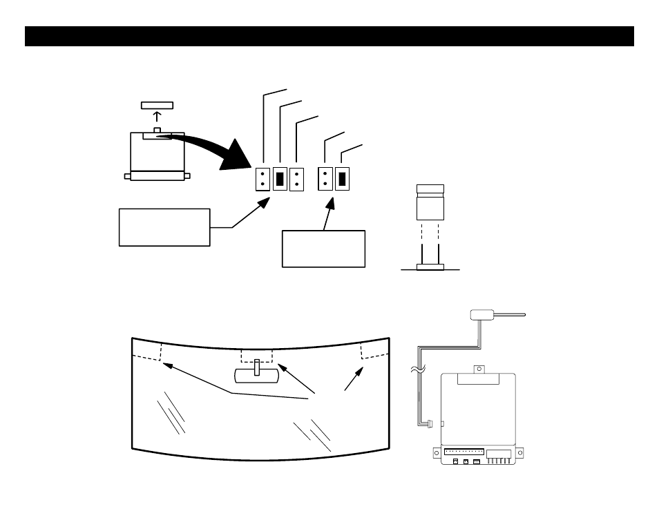
JUMPER PIN & ANTENNA DIAGRAMS
Jumper pins are used to configure the operation of the on board multi-function output PINK/WHITE wire and the Parking
Light WHITE wire. See the diagram below for Jumper Pin configurations.
JUMPER
PLUG
SIDE VIEW
JUMPER
PINS
JP1 JUMPERS:
IGN 2 (DEFAULT)
ACC 2
(-) NEGATIVE PARKING LIGHT (500 mA)
+12V (10A) PARKING LIGHT (DEFAULT)
IGN2 / ACC2 / STR2
PINK WHITE
JP2 JUMPERS:
PARKING LIGHT
OUTPUT
CONTROL MODULE
STARTER 2
WINDSHIELD
ANTENNA
LOCATIONS
EZ-30/10
RECOMMENDED
ANTENNA / RECEIVER GUIDE
19
See also other documents in the category Crimestopper Security Products Car alarm:
- EZ-95FM (32 pages)
- CS-865RKE (12 pages)
- RS800 Series II (4 pages)
- CS-2008PC (19 pages)
- EZ-777 TW2 (16 pages)
- EZ-64TW1 (28 pages)
- CS-2011RS IV (30 pages)
- CS-2011RS IV (28 pages)
- SERIES II CS-2004DC II (27 pages)
- CS-2003DC SERIES II (18 pages)
- CS-2004TW1 (24 pages)
- CS-2004DC (20 pages)
- RS901 (13 pages)
- EZ-33DP (16 pages)
- CS-2016FM (21 pages)
- RS1905FM (32 pages)
- CS-2000DP-TW2 (24 pages)
- CS-2001 (12 pages)
- CS-2004DC (24 pages)
- CS-2000 (16 pages)
- CS-883 OEM (12 pages)
- CS-855RKE (12 pages)
- CS-2014TW2 (20 pages)
- RS-1704TW2 (20 pages)
- EZ-84FM (20 pages)
- RS900 (28 pages)
- Series IV Super Rage CS-2011RS (16 pages)
- EZ-10 (12 pages)
- CS-2000DPII TW2 (24 pages)
- CS-2205 (32 pages)
- EZ-30DP (29 pages)
- CS-2013FM (26 pages)
- CS-2100 (9 pages)
- CS-2001FC (20 pages)
- CS-2012DP-TW1 (32 pages)
- CS-2012DP-TW1 (32 pages)
- FS-20 (12 pages)
- CS-2011RS (16 pages)
- CS-882 (10 pages)
- CS-8050 (8 pages)
- TN-4011 (14 pages)
- GARGOYLE CS-2001FC (17 pages)
- EZ-45DP (14 pages)
- RS-1804FM (20 pages)