7step 6: attach the pulley arms – Bowflex Xtreme 2 User Manual
Page 9
7
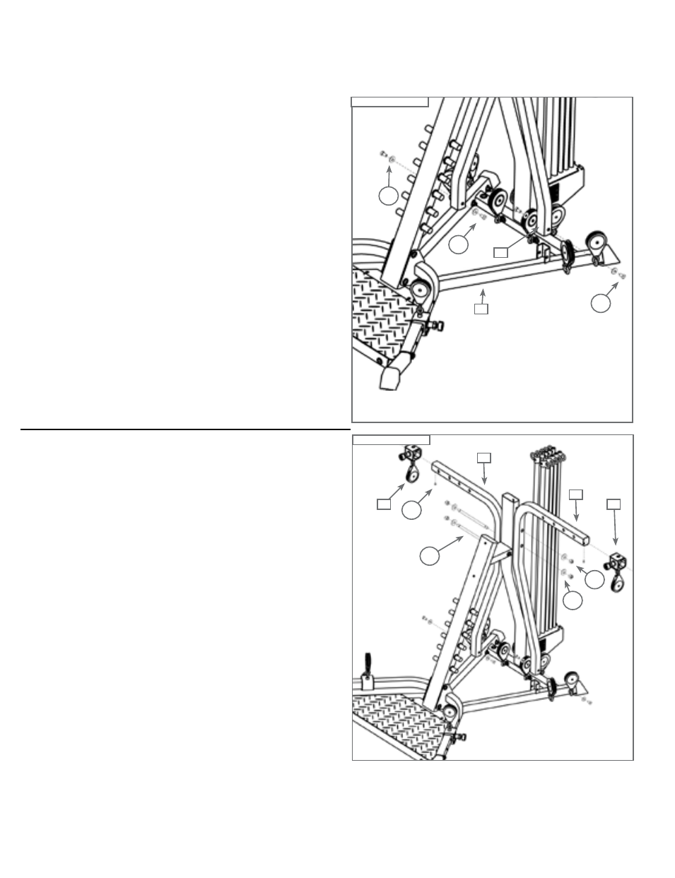
Step 6: Attach the Pulley Arms
Locate the following items:
• Items #12 and #13 - Right and Left Pulley Arms
• From Step 5 - Main Assembly
• Item #F - (4) 3/8" X 3/4" Hex Head Bolts
• Item #O - (4) 3/8" Washers
Place the Right Pulley Arm (Item #12) onto the bracket on
the Right Frame Rail (Item #2), as shown in Figure 6.
Note: Make sure that the bolt holes in the Pulley Arms are
facing away from the Rod Pack.
Place (2) 3/8" Washers (Item #O) over (2) 3/8" X 3/4"
Hex Head Bolts (Item #F) - one washer per bolt. Thread
the bolts through the bolt holes in the Frame Rail bracket
and the Right Pulley arm, loosely securing the arm in
place, as shown in Figure 6.
Repeat this process for the Left Pulley Arm (Item #13).
Do not tighten hardware from Step 6 at this time.
Step 7: Secure Pulley Arms and Attach Chest Pulleys
Locate the following items:
• Item #14 - (2) Chest Pulleys
• From Step 6 - Main Assembly
• Item #C - (2) 1/4" X 1/2" Socket Head Cap Bolts
• Item #K - (2) 1/2" X 9 1/2" Threaded Studs (Labeled Bolts)
• Item #P - (4) 1/2" Washers
• Item #S - (4) 1/2" Nylock Nuts
Line up the holes in the Right Pulley Arm (Item #12)
and the Left Pulley Arm (Item #13) with the holes on the
Lower Lat Tower (Item #1), as shown in Figure 7.
Slide the (2) 1/2" X 9 1/2" Threaded Studs (Item #K) all
the way through the both Pulley Arms and the Lower Lat
Tower, and secure tightly, using (4) 1/2" Washers (Item
#P) and (4) 1/2" Nylock Nuts (Item #S) over both ends of
each Threaded Stud.
Slide one Chest Pulley (Item #14) over the Right Pulley
Arm, and the other Chest Pulley over the Left Arm. Each
Pulley can rest in any of the four holes in the Pulley Arms.
Place (1) 1/4" X 1/2" Socket Head Cap Bolt (Item #C)
through the hole on the underside of each Pulley Arm - this
prevents the Slider Pulleys from sliding off.
Do not tighten hardware from Step 7 at this time.
Figure 7
K
P
14
14
S
C
13
12
Figure 6
12
O
F
F
2