Engine, P.t.o, Figure 20 – MTD 675 thru 689 User Manual
Page 8: Belt replacement, 1 1 gear box (self-propelled models only), Self-propelled models only), Figure 19
Attention! The text in this document has been recognized automatically. To view the original document, you can use the "Original mode".
1 1
Gear Box (Self-Propelled Models Only)
—The
gear
box
is
lubricated
with
3
ounces
of
High
Tenp.
(450°
F.)
grease.
Order
part
number
737-0223.
Pf
riodically
check
lubricant
level
by
removing
the
two
se
f-tapping
screws on the gear box cover and lifting off t ie cover.
Do not change grease; simply add if necessary.
ENGINE
Refer to the separate engine manual fo' engine
maintenance instructions.
Maintain
engine
oil
as
instructed
in
the
¡separate
engine
manual
packed
with
your
unit.
Read
and
follow
instructions carefully.
Service
air
cleaner
every
25
hours
under
noi
mal
con
ditions.
Clean
every
few
hours
under
extremely
dusty
conditions.
Poor
engine
performance
and
flooding
usually
indicates
that
the
air
cleaner
should
be
ser
viced.
To
service
the
air
cleaner,
refer
to
the
separate
engine manual packed with your unit.
The
spark
plug
should
be
cleaned
and
the
gap
reset
once
a
season.
Spark
plug
replacement
i;;
recom
mended
at
the
start
of
each
season;
chec<
engine
manual for correct plug type and gap specific itions.
Clean
the
engine
regularly
with
a
cloth
or
brush.
Keep
the
cooling
system
(blower
housing
area)
clean
to
permit
proper
air
circulation
which
is
essential
to
engine
performance
and
life.
Be
certain
to
re
¡move
all
dirt and combustible debris from muffler area
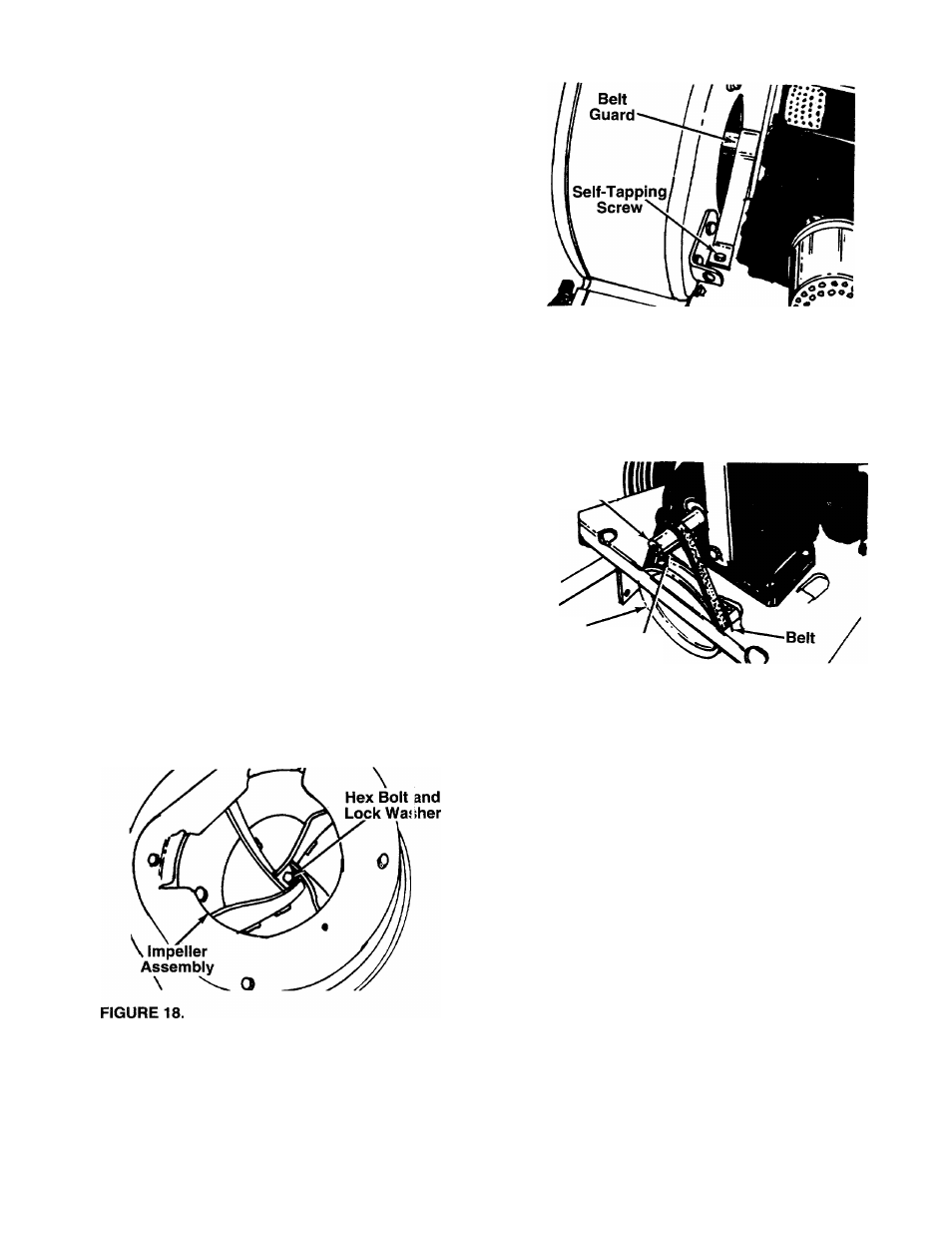
BELT REPLACEMENT
(Self-Propelled Models Only)
1.
Remove the nozzle or impeller guard from front of
blower housing.
2.
Remove
hex
bolt
and
lock
washer
from
center
of
impeller.
See
figure
18.
A
9/16"
socket
wrench
with extension is needed.
3.
4.
Remove
hand
knob
and
cupped
washer
from
top
of housing.
Remove
two
self-tapping
screws
which
hold
the
belt
guard.
See
figure
19.
A
3/8”
wench
is
required. Lift off belt guard.
FIGURE 19.
5.
Slide
belt
off
the
impeller
pulley.
Slide
housing
and
impeller
off
engine
crankshaft.
Be
careful
to
not lose square key. See figure 20.
Engine
Crankshaft
P.T.O.
Pulley Square
Key
FIGURE 20.
6.
Slide
impeller
and
blower
housing
assemblies
off
crankshaft.
7.
Remove
belt
from
P.T.O.
pulley
and
install
new
belt. See figure 20.
NOTE:
When reassembling the new belt, the aid of
another person will be helpful.
8.
Turn
the
crankshaft
until
the
keyway
on
shaft
is
directly
on
top.
While
holding
housing
assembly
and
impeller
assembly,
line
up
the
keyway
on
the
pulley
with
the
key
on
the
crankshaft,
and
slide
housing and impeller assemblies onto crankshaft.
9.
Secure
impeller
to
crankshaft
with
hex
bolt
and
lock washer, removed in step 2. Tighten securely.
10.
Slip belt over impeller pulley. Reassemble the
belt guard.
11.
Secure blower housing with hand knob and wash
er.
12.
Reassembie the nozzle or impeller guard.