Figure 15.—optionai tow bar, Installation of optional tow bar, Operation – MTD 675 thru 689 User Manual
Page 6: Before starting engine, To start engine
Attention! The text in this document has been recognized automatically. To view the original document, you can use the "Original mode".
I I
Cupp^ Washen
Flat Washer
Hand Knob
FIGURE 14.
Direc’ional
Disci large
Assembly
Hex Nut
(C)
Hex
Bolt (A)
Truss
Machine
Screw (D),
Cupped
Washer (H)
Shouider
Spacers (B)
Lock
Washer (E)
yt ■
^^Shouider
Nut (F) Bon (Q)
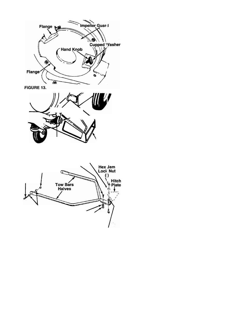
FiGURE 15.—Optionai Tow Bar
4.
Lift up and out on the housing and rotate it 105°
clockwise.
Chute
opening
should
be
to
the
right
hand side when viewed from the front of unit. See
— figure 13.
5.
Place
the
impeller
guard
into
flanges
on
front
of
housing. Line up hole in guard with hole on hous
ing.
Secure
with
one
hand
knob
and
cupped
washer
(cupped
side
of
washer
against
the
impeller guard). See figure 13.
Place
the
directional
discharge
assembly
over
chute
opening.
Secure
with
one
hand
knob,
cupped
washer
and
flat
washer,
and
the
thumb
screw
and
cupped
washer.
The
cupped
side
of
washer
goes
against
the
flat
washer.
See
figure
14.
INSTALLATION OF OPTIONAL TOW BAR
1.
Remove
the
self-tapping
screws
on
each
side
of
frame.
Refer
to
illustration
on
page
10,
reference
number 42.
2.
Place one bar half in position on frame of vacu
um.
Place
one
shoulder
spacer
(B)
between
frame
and
tow
bar.
Next,
place
shoulder
spacer
(B) and hex bolt (A) through tow bar and frame.
-------- Secure with hex nut (C). See figure 15. Repeat
on other side.
Clipped
Waiiher (H)
3.
Secure
the
two
tow
bar
ends
together
with
truss
machine
screw
(D),
lock
washer
(E)
and
hex
nut
(F). See figure 15.
To
attach
the
tow
bar
to
a
hitch,
place
the
shoulder
bolt
(G)
up
through
the
tow
bar.
Place
one
cupped
washer
(H)
on
the
shoulder
bolt,
then
the
hitch
plate
and
the
other
cupped
washer.
Cupped
side
of
the
washers
must
be
against
the
hitch
plate.
Secure
with
hex jam lock nut (I). See figure 15.
OPERATION
BEFORE STARTING ENGINE
Service
engine
with
gas
and
oil.
See
engine
manual
packed
with
vacuum
for
complete
instructions
for
care
and maintenance of engine. Read directions c irefully.
▲
WARNING:
Revolving
blades
--
keep
hands away from all openings.
TO START ENGINE
After
the
engine
has
been
properly
fueled
and
oiled
(refer
to
engine
operating
and
maintenance
instruc
tions), start engine as follows.
1. Move choke lever on engine to CHOKE position.
(A warm engine may not require choking.)
2.
Move throttle control lever on engine to FAST
position.