Tine assemblies model 381 only – MTD 214-381-000 User Manual
Page 7
Attention! The text in this document has been recognized automatically. To view the original document, you can use the "Original mode".
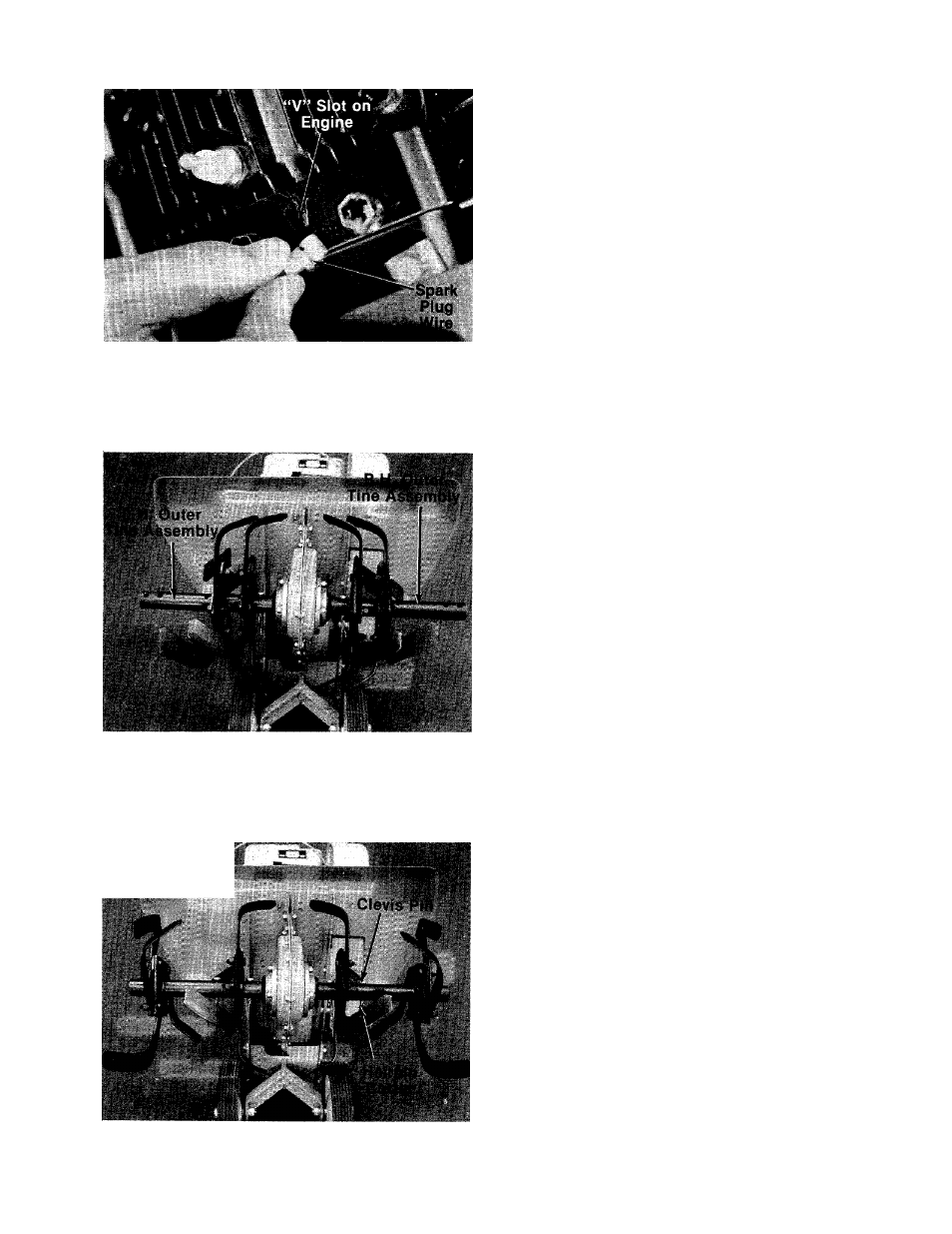
3. Disconnect the spark plug wire from spark
plug to prevent accidental starting. Secure
end of spark plug wire in the “V” slot on the
— engine. See figure 9. With the clutch lever in
neutral position, pull starter cord several
times. The tines should not turn. If they do,
remove the hairpin cotter and remove the con
trol rod from the clutch lever. Thread the con
trol rod in or out of the ferrule as necessary.
Replace and check again for correct adjust
ment.
FIGURE 9.
TINE ASSEMBLIES
Model 381 Only
Check to be certain the tine assemblies are on the
tine shaft so that the sharp edge enters the soil
first. See figure 11.
Model 385 Only
The inner tine assembiies are instaiied at the fac
tory. The outer tine assemblies are inverted. See
-figure 10. The right hand outer tine assembly has
been removed, inverted and slid onto the left hand
side for shipping only. The same has been done
with the left hand outer tine assembly.
FIGURE 10.
-
J Ï-WÏW A ..W
'*i
Remove both outer tines. Place tine removed from
left hand side on right hand shaft. Place tine
removed from right hand side on left hand shaft.
Make sure that the sharp edge of the tines enters
the soil first. Secure with clevis pins (P) and inter-
■ nal cotter pins (Q). See figure 11.
FIGURE 11.