Note, Figure – MTD 24596L User Manual
Page 6
Attention! The text in this document has been recognized automatically. To view the original document, you can use the "Original mode".
NOTE
Right and left hand side is determined
from behind the edger, in the opera
tor's position.
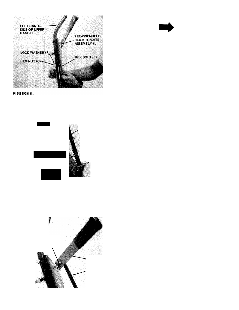
7.
Place preassembled clutch plate assembly (L)
on the left hand side of upper handle. Secure
in place with hex bolts (E), lock washers (F)
and hex nuts (G). See figure 6.
COMPRESSION
SPRING (H)
SPINDI ^
brack
“-
ASSEMBLY
CLUTCH ROD { h )
COTTER
PIN IJ)
8.
Place compression spring (H) over straight end
of clutch rod (N). Place end of rod in spindle
bracket assembly and secure with cotter pin (J).
See figure 7.
FIGURE?.
COTTER
PIN(J)
a.
CLUTCH
LEVER
CLUTCH
ROD (N)
9. Place hook end of clutch rod (N) in clutch
lever. Secure with cotter pin (J). See figure 8.
FIGURES.