Sharpening or replacing chipper blades, Sharpening or replacing shredding blade, Figure 10 – MTD 242A641-000 User Manual
Page 7: All units
Attention! The text in this document has been recognized automatically. To view the original document, you can use the "Original mode".
V
SHARPENING OR REPLACING CHIPPER BLADES
1.
Disconnect
spark
plug
wire
and
move
it
away
from spark plug.
2.
Remove
the
flail
screen
as
instructed
in
previous
section.
3.
Remove
the
chipper
chute
by
removing
three
hex
nuts
and
washers.
A
1/2"
wrench
is
required.
See
figure 9.
NOTE: When reassembling, the cupped washer goes
on the bottom of the chipper chute with the cupped
side against the chute.
4.
Rotate
the
impeller
assembly
by
hand
until
you
locate
one
of
the
chipper
blades
in
the
chipper
chute
opening.
Remove
the
blade,
using
a
3/16"
alien wrench on the outside of the blade and 1/2"
wrench
on
the
impeller
assembly
(inside
the
housing). See figure 10.
5.
Remove the other blade in the same manner.
FIGURE 10.
Replace
or
sharpen
blades.
If
sharpening,
make
cer
tain
to
remove
an
equal
amount
from
each
blade.
Reassemble in reverse order.
Make
certain
blades
are
reassembled
with
the
sharp
edge
facing
the
direction
shown
in
figure
10
(sharp
edge
is
assembled
toward
the
slotted
opening
in
the
impeller assembly).
SHARPENING OR REPLACING SHREDDING BLADE
The
shredding
blade
may
be
removed
for
sharpening
or replacement as follows.
1.
Disconnect
spark
plug
wire
and
move
it
away
from spark plug.
2.
Remove
the
six
hex
lock
nuts
and
lock
washers
from
the
housing
weld
bolts
using
a
1/2"
wrench.
Remove the hopper assembly
3. Remove the back-up plate.
NOTE: When reassembling, make certain the open
ing on the back-up plate is toward the bottom of the
unit. The back-up plate may be reversed to provide a
new cutting edge.
Allen
Screws
Torque
epad©
Wrench
FIGURE 11.-Model 242A640 & 242A641 Shown
4.
Loosen
the
two
hand
knobs
and
cupped
washers
which
secure
the
chute
deflector,
and
raise
the
chute deflector.
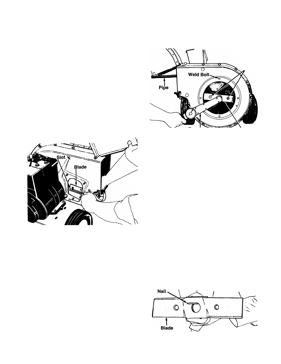
5.
Keep
the
impeller
assembly
from
turning
by
inserting
a
1/2"
or
3/4"
diameter
pipe
through
the
flail
screen,
or
remove
the
flail
screen,
and
insert
a piece of wood (2 x 4) into the chute opening.
6.
Models 242A645 and 242A648 only:
Remove
the
two
outside
screws
on
the
blade,
using
a
3/16" alien wrench and a 1/2" wrench.
7.
All Units:
Remove
the
blade
by
removing
the
center bolt, lock washer and flat washer.
NOTE: Use caution when removing the blade to avoid
contacting the weld bolts on the housing.
When
sharpening
the
blade,
follow
the
original
angle
of grind as a guide. It is extremely important that each
cutting
edge
receives
an
equal
amount
of
grinding
to
prevent
an
unbalanced
blade.
An
unbalanced
blade
will
cause
excessive
vibration
when
rotating
at
high
speeds and may cause damage to the unit.
The
blade
can
be
tested
for
balance
by
balancing
it
on
a
round
shaft
screwdriver
or
nail.
Remove
metal
from
the
heavy
side
until
it
is
balanced
evenly.
See
figure 12.
FIGURE 12.-Model 242A640 & 242A641 Shown