B. spark arrestor and spark plug, M m m ïï – Poulan 3300 User Manual
Page 17
Attention! The text in this document has been recognized automatically. To view the original document, you can use the "Original mode".
5.) Correct Depth Gauges
a.) Place depth gauge tool over each cutter
depth gauge. Figure 31.
File level with the flat file if depth gauge is
higher than the depth gauge tool.
Maintain rounded front corner of depth
gauge with a flat file. Figure 31 &32.
NOTE:
The very top of the depth gauge
should be flat with the front half rounded
off with a flat file.
b.)
c.
A
warning
Depth gauge tool is required to insure proper depth
gauge. Filing the depth gauge too deep will increase
the chance of kickback which can result in serious
injury.
b. CHAIN REPLACEMENT
1.
) Useonly the Low-KickChaIn specified for
your saw in “Specifications,” forrepiace-
ment chain.
2. ) Replace the chain when cutters or links
break.
3. ) See a qualified service dealer to replace
and sharpen individual cutters for match
ing your chain.
4. ) Always have a worn sprocket replaced by
a qualified service dealer when installing
a new chain to avoid excessive wear to the
chain.
GUIDE BAR MAINTENANCE
•
Conditions which can require guide bar
maintenance:
— saw cuts to one side
— saw has to be forced through a cut
— inadequate supply of oil to bar and chain.
•
Check the condition of theguidebareachtime
the chain is sharpened.
A worn guide bar will
damage the chain and make cutting more difficult.
• Replace the guide bar when:
— the inside groove of the guide bar rails is
worn.
— the guide bar is bent or cracked.
e
Use only the Reduced-Kickback Guide Bar
specified for your saw In "Specifications,” for
replacement.
a. Remove the guide bar to service.
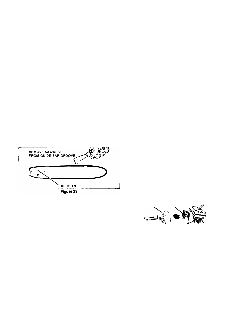
b.
Clean oil holes at least once for each five
hours of operation. Figure 33.
c.
Remove sawdust from the guide bar
groove periodicaily with a putty knife or
a wire. Figure 33.
d.
Remove burrs by filing the side edges
of the guide bar grooves square with a
flat file. Figure 34.
e. - Restore square edges to an uneven rail
top by filing with a flat file. Figure 34.
M M M ÏÏ
1
CORRECT
GUIDE BAR
GROOVE
WORN GROOVES
FILE
EDGES'
SQUARE
Figure 34
B. SPARK ARRESTOR AND SPARK PLUG
1. SPARK ARRESTOR
• Carbon deposits build up on the spark ar
restor,
as the saw Is used and must be removed to
avoid creating afire hazard or causing engine dam
age.
• Replacethesparkarrestorif breaks occur.
• Keep the spark arrestor clean at all times.Clean.
— as required
— at least once for each 25-30 hours of
operation
Items required:
— wire brush,
— 3/8" wrench
a. Disconnect the spark plug wire.
b. Remove the heat shield. Figure 35.
c. Remove the screen from the diffuser.
d. Clean the screen with a wire brush or replace if
breaks are found.
e. Reassemble parts.
HEAT SHIELD DIFFUSER
SPARK ARRESTOR! SCREEN
Figure 35
2. SPARK PLUG
• Replace the spark plug when necessary;
• If you perform this maintenance yourself, note
the “Caution” below.
I
CAUTION:
i
Do not mix chrome-colored fan
housing screws with the black-colored cylinder
shroud screws. Other than color, these screws are
similar in appearance; but if interchanged, they
can strip out and/or cause permanent engine
damage.
17