Attaching the upper handle (hardware b), Attaching the control box, Securing the cables (hardware 0) – MTD 113-060A000 THRU 113-062D000 User Manual
Page 6
Attention! The text in this document has been recognized automatically. To view the original document, you can use the "Original mode".
1 1
ATTACHING THE UPPER HANDLE (Hardware B)
1. Place the upper handle in position over the lower han
dle. The hole in the side of the blade control handle
(attached to the upper handle) must be on the left side.
- 2. Secure the upper handle to lower handle using the
curved head bolts; spilt washers and hex nuts as
shown in figure 2.
FIGURE 2.
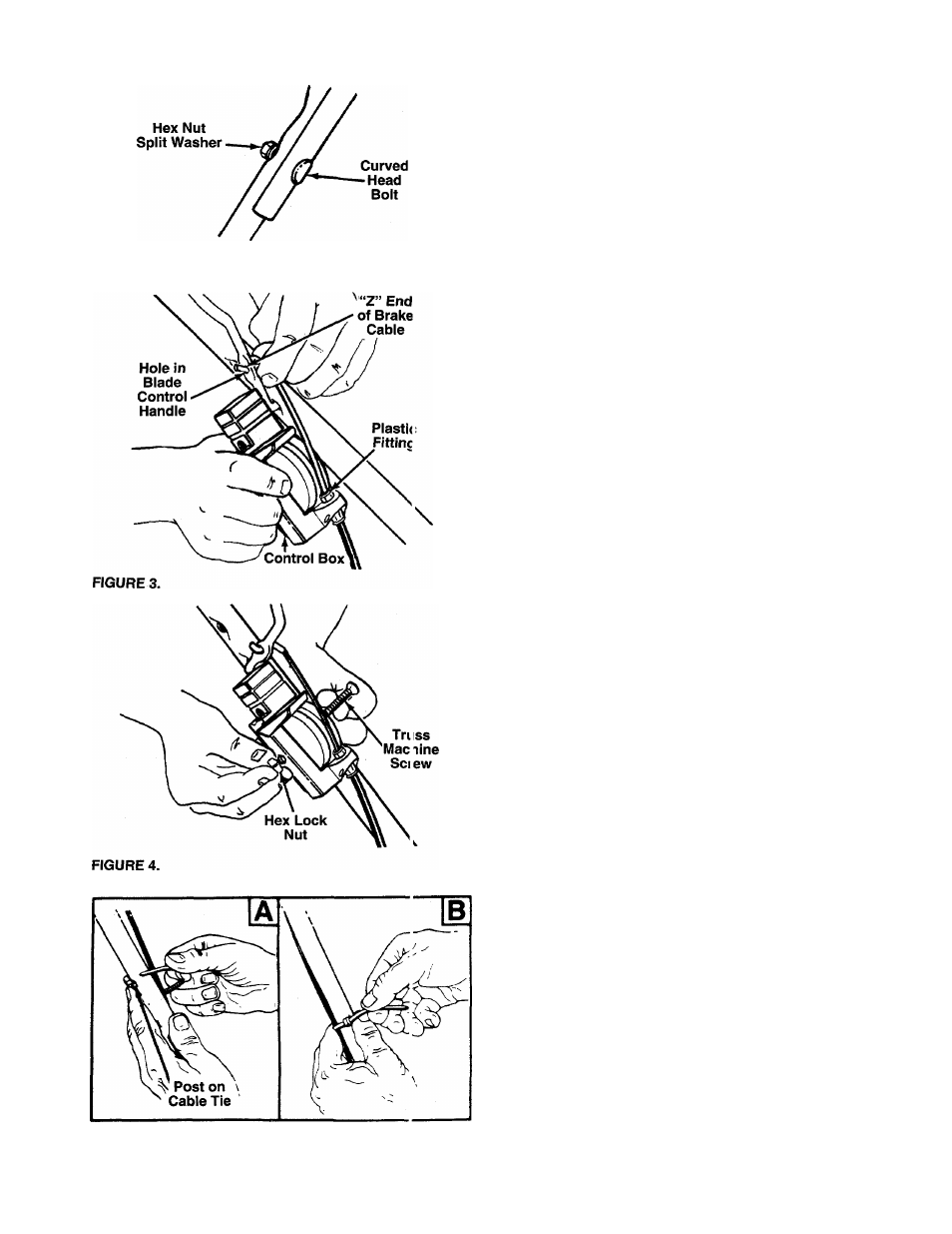
ATTACHING THE CONTROL BOX
One end of the throttle control cable and one end of the
brake cable are attached to the engine. The other ends are
attached to the control box. Attach the control box to the
upper handle as follows.
- 1. Remove the truss machine screw and hex lock nut from
the middle of the control box using a phillips screwdriv
er. Place your finger over the hex lock nut to hold it
inside the control box so you can unscrew the truss
machine screw.
2. Make certain the blade control handle is on top of the
upper handle.
3. Route the control box (with cables attached) under the
lower handle. Make certain the cables are not twisted.
NOTE:
If the brake cable Is not attached to the control box,
insert the “Z” end of the cable into the control box as shown
in figure 3. Push the piastic fitting until It locks into the con
trol box.
4. Holding the control box near the left side of the upper
handle (control box must be inside the handle), hook
the “Z” end of the brake cable into the control handle
from the outside to the inside. See figures 3 and 4.
5. Place the control box on the upper handle just below
— the end of the control handle as shown in figure 4.
Secure with hardware removed in step one by placing
hex lock nut into the indent on the inside of the control
box. Screw the truss machine screw into the hex lock
nut.
SECURING THE CABLES (Hardware 0)
Secure the cables to the left side of the handle as follows.
A
WARNING: When attaching the control
cables, the cables must be routed to avoid
contact with all sharp edges and hot surfaces
to prevent damage to the cables, which will
render the controls inoperative.
FIGURE 5.
1. Insert posts on cable ties into holes provided on the
inside of the handle, one on the upper handle and two
on the lower handle. The holes may be either on the
inside or outside of the handles. See figure 5A.
2. Secure the cables with the cable ties. See figure 5B.
Trim excess ends of cable ties.