Assembly instructions, Unpacking, Attaching the lower handle (hardware a) – MTD 113-060A000 THRU 113-062D000 User Manual
Page 5: Ahaching the lower handle (hardware a)
Attention! The text in this document has been recognized automatically. To view the original document, you can use the "Original mode".
ASSEMBLY INSTRUCTIONS
IMPORTANT: This unit is shipped WITHOUT GASOLINE
or OIL. After assembly, service engine with gasoiine
and oii as instructed in the separate engine manuai
packed with your unit.
NOTE:
Reference to right or left hand side of the mower is
obsen/ed from the operating position.
Toois Required for Assembiy
(1) 1/2" Wrench
(2) 9/16" Wrenches
(1) Phillips Screwdriver
(1) Adjustable Wrench
(Two 6" Adjustable Wrenches may be used instead of the
above.)
Lower
Handle
Use
This
Hole
Crowned 1 (Cupped
Side
\
i Side
Rear Baffle
(Models 040 thru
Onhi);.;.
Axle Bolt
Hex Nut
Hex Nut
Cupped
Washer
Spacer
Use
Cupped
This',
Washer Hole
FIGURE 1.—Models 040 thru 042 Shown
UNPACKING
1. Remove the lawn mower from the carton by opening
the top flaps and lifting the unit out. Be careful of the
staples. Make certain all parts and literature have been
removed from the carton before the carton is discarded.
2. Disconnect and ground the spark plug wire against the
engine.
3. Stretch out the control cables behind the mower and
place on the floor. Be careful not to bend or kink the
cables at any time during assembly.
4. Remove page four from this manual and lay the contents
of the hardware pack on the illustration for identification.
NOTE:
ALL MODELS
—
The handle on your mower can be
adjusted to two different height settings. To raise the height
of the handle attach the lower handle so that the flat part of
the handle is facing downward, as shown in figure 1 and 1B.
To lower the height of the handle rotate handle so that the
flat part of the handle faces upward.
ATTACHING THE LOWER HANDLE (Hardware A)
Models 030 thru 042 only:
1. Raise the rear of the deck and block securely.
2.
Models 040 through 042 only:
Place the rear baffle in
position inside the rear of the deck. Use one axle bolt
and hex nut on each side of the rear of the deck to
secure baffle temporarily so you can attach the lower
--------handle. See figure 1.
NOTE:
Remove axle bolt and nut when assembling the
wheels, page 7.
3. Insert the ends of the lower handle through the slots in
the rear of the deck.
4. Place one cupped washer on hex bolt (crowned side of
washer goes against the head of the hex boit).
5. Place one spacer between forward hole in baffie (or
deck on Modeis 030 through 032) and bottom hole in
lower handle.
NOTE:
Use a screwdriver to pry the handle away from the
baffle slightly in order to insert the spacer. The screwdriver
can also be used to align the holes in the next step.
6. Insert hex bolt through forward hole in deck, baffle
(Models 040 through 042 only), spacer and lower han
dle. Secure with cupped washer (cupped side against
the handle) and hex nut, finger tight only.
7. Repeat steps 4 through 6 to attach the other side of the
handle. Then tighten securely the two bolts and nuts
used to attach the handle.
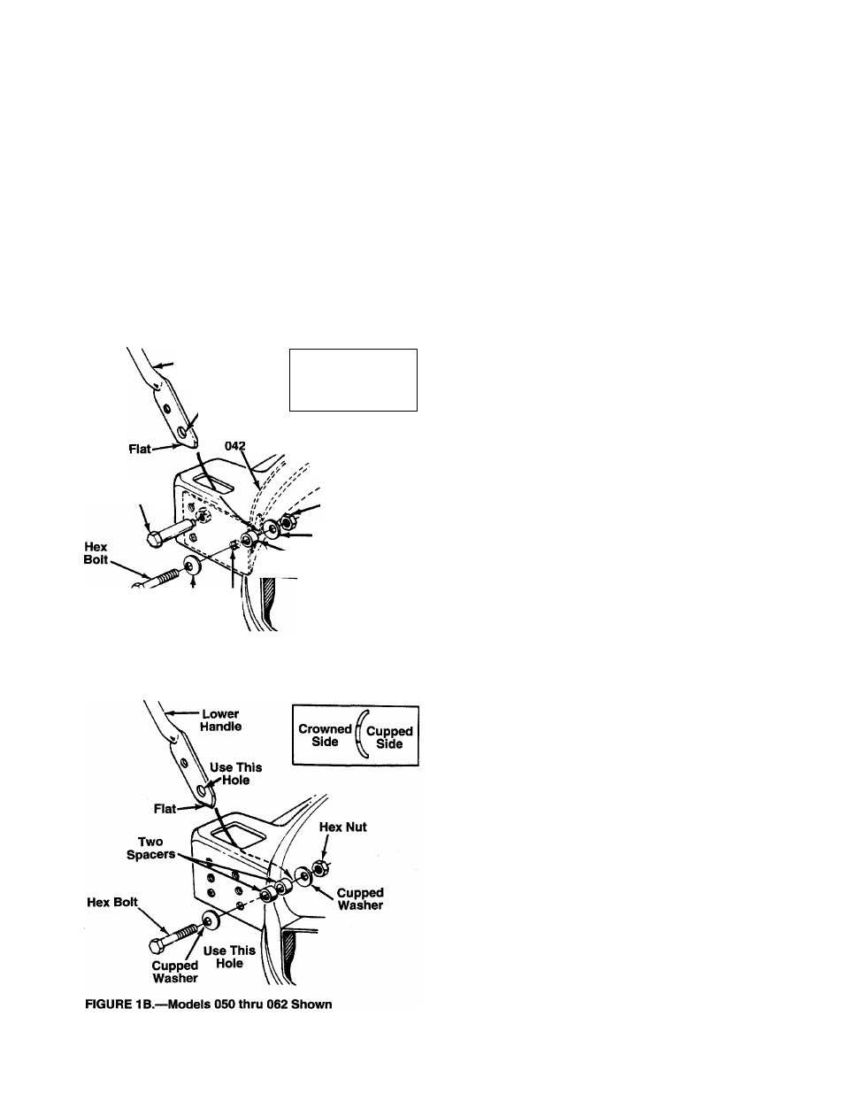
AHACHING THE LOWER HANDLE (Hardware A)
Models 050 thru 062 only:
1. Raise the rear of the deck and block securely. Insert
the ends of the lower handle through the slots in the
rear of the deck.
2. Place one cupped washer on hex bolt (crowned side of
washer goes against the head of the hex boit).
3. Using the inside set of hoies in the rear of the deck,
insert hex bolt through bottom hole as shown in figure
--------IB.
4. Place two spacers on hex bolt. Then insert hex bolt
through bottom hole in handie. Secure with cupped
washer (cupped side against the handle) and hex nut,
finger tight only.
5. Repeat steps 2 through 4 to attach the other side of the
handle.
6. Tighten both hex bolts and nuts securely.