Warning i, Note, Adjustments – MTD 218-402-000 User Manual
Page 9
Attention! The text in this document has been recognized automatically. To view the original document, you can use the "Original mode".
A
i
WAF
WARNING I
Do not push down on the handles so
that the wheels are lifted off the
ground while the tine ciutch is en
gaged, or the tiiler could move back
ward and cause personal injury.
For best results, it is recommended the garden be tilled
twice (lengthwise, then widthwise) to pulverize the soil.
FIGURE 15.
2. When breaking up sod and for shallow cultivation,
use the setting which gives IV
2
" of tilling depth
(second hole from the top). Place the side shields
in their lowest position. For further depth, raise the
depth bar and side shields and make one or two
more passes over the area.
3. When tilling loose soil, depth bar may be raised
to its highest position (use bottom adjustment hole)
to give the deepest tilling depth. Raise the side
shields to their highest position.
4. To transport tiller, lower the depth bar (use top ad
justment hole).
To adjust the depth bar, remove the clevis pin and hair
pin cotter. See figure 14. Move the depth bar to the
desired setting.
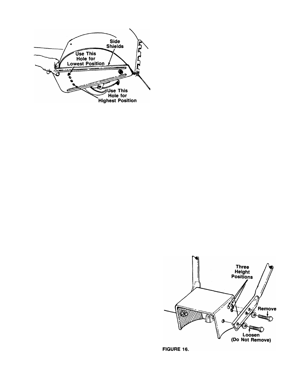
To adjust the side shields, remove the hex nut and
belleville washer from the front and loosen the rear nut.
See figure 15. Pivot the side shield to the desired posi
tion. Replace hex nut and belleville washer. Tighten
securely.
To operate the tiller:
1. Select the depth bar setting.
2. Start engine as instructed on page 8.
3. Engage drive and tine clutch levers.
WARNING
i
Engage wheel drive before engaging
the tine clutch lever.
NOTE
To transport tiller, do not engage
the tine clutch lever. Engage the
wheels only.
ADJUSTMENTS
HANDLE ADJUSTMENT (Models 402 and 404)
The handle may be adjusted to one of three height posi
tions. See figure 16. To adjust the handle:
1. Loosen the bolts on the ends of the handle.
2. Remove the hex bolts from the handle which are
closest to the operator.
3. Pivot the handle to the desired position and replace
the hardware. Tighten securely.