Handle adjustment (model 405), Belt tension adjustment—drive and ti ie clutches, Note – MTD 218-402-000 User Manual
Page 10: Lubrication
Attention! The text in this document has been recognized automatically. To view the original document, you can use the "Original mode".
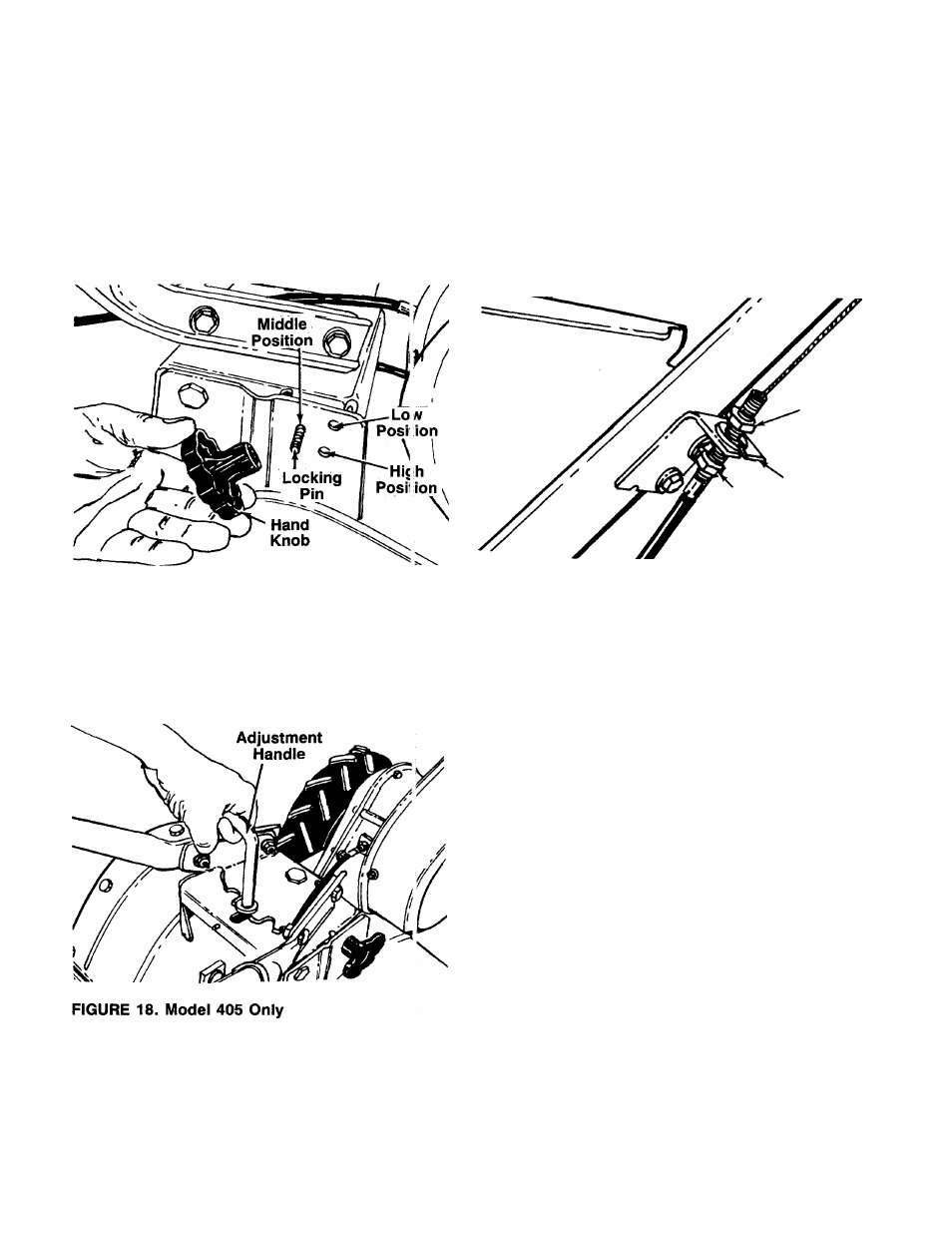
HANDLE ADJUSTMENT (Model 405)
The handle may be placed in one of nine differen posi
tions. The handle may be adjusted to one of three
height positions, and also may be adjusted to be n line
with the tiller, or swung to the left or right so the op arator
is not walking in the freshly tilled soil.
To adjust the handle height, remove the hand kno o and
locking pin shown in figure 17. Select one of the three
adjustment holes and reassemble.
FIGURE 17. Model 405 Only
To adjust the handle position from side to side, Ic osen
the adjustment handle by turning it counterclockwise
several turns. Pull the adjustment handle backward and
pivot the tiller handle to desired position. Releaso and
tighten the adjustment handle. See figure 18.
BELT TENSION ADJUSTMENT—Drive and Ti ie
Clutches
Periodic adjustment of the belt tension may be req jired
due to normal stretch and wear on the belt. Adjust Tient
is needed if the tines seem to hesitate while tillinc, but
the engine maintains the same speed.
To adjust, loosen the hex nuts at the cable bracket on
the handle. See figure 19. With the clutch lever re
leased as shown in figure 12, adjust the bottom nut so
that there is only a slight amount of slack in the control
wire. Tighten the upper nut against the bracket.
NOTE
Do not overtighten control wire.
Too much tension may cause it to
break.
Upper
Nut
Cable
Bottom Bracket
Nut
FIGURE 19.
CARBURETOR ADJUSTMENT
AC
WARNING
i
If any adjustments are made to the
engine while the engine is running,
(e.g.
carburetor),
disengage
all
clutches and tines. Keep clear of all
moving parts. Be careful of heated
surfaces and muffler.
Never make unnecessary adjustments. The factory set
tings are correct for most applications. If adjustments
are needed, refer to the separate engine manual
packed with your tiller.
LUBRICATION
Chain Cases—
The chain cases are pre-lubricated and
sealed at the factory. They require no checking unless
the chain cases are disassembled. To fill with grease,
lay the left half of the chain case on its side. Add 12
ounces of plastilube #0 grease to the tine chain case
or 10 ounces to the wheel chain case. Assemble the
right half to it. This grease can be obtained at your
nearest authorized dealer. Order part number
737-0133.
10