Assembly 217-100, Clutch control lever assembly, Check list before operation – MTD 219-250 User Manual
Page 4: Starting your tiller
Attention! The text in this document has been recognized automatically. To view the original document, you can use the "Original mode".
ASSEMBLY 217-100
Your rotary tiller is shipped complete in a single carton.
The tines, wheels, handles, controls and depth bar are to be
assembled. This is done in the manner described below.
TINES
- Mount tines on tine shaft as shown. Tines must
be mounted with the cutting edges facing the front. The
tiller will not operate properly unless the sharpened sur
face of the tines enter the soil first. Secure tines in posi
tion on tine shaft with cap screws (47), and nuts (46).
NOTE:
Dust pads (68 8t 69) are provided in screw pack.
These must be assembled as shown.
WHEELS - Insert axle bolts (31) into wheel hubs. Secure
with locknuts (32) tightened only enough to allow free move
ment of the wheels (26). Attach wheel and axle assemblies
to outside of tiller legs (10 8t 11). Fasten with locknuts (32)
as shown.
HANDLE- Assemble the handle brackets (122) to the han
dle (116) with hex head screw (127), lockwashers (44) and
hex nuts (126). Do Not Tighten. Place the handle brackets
(122) in the tail piece slots. Fasten the lower hole in the
handle brackets to the frame with a carriage bolt 5/16
-18
X 3/4 Ig. (50), lockwasher (51) and hex nut (57). Tight
en all screws and nuts.
CLUTCH CONTROL LEVER ASSEMBLY
LOCKOUT LEVER-Place the hex head screw %-20 x 1
%
(128) through the hole in the tab below the slot in the han
dle panel from the right hand side. Assemble in this order:
Rubber washer, lock out rod (rod bracket to the front), steel
washer and lock nut. Tighten until rubber washer compresses
slightly.
CLUTCH CONTROL ASS’Y-
Screw the ferrule (120) on the
threaded end of the lock out rod (119) until about '/
2
” of the
threads show. Insert the ferrule through the control lever
(15), fasten with flat washer (123) and cotter hairpin (124).
Put the lockout handle in the neutral position. Insert the
lockout rod in the bracket on the lockout lever and secure
with a cotter hairpin through the center of the bracket. Ad
just the ferrule so both belts are slack when the lockout
lever is in the neutral position.
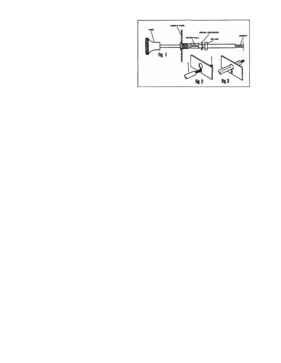
THROTTLE-T
o
assemble the throttle push the black plastic
knob in all the way then pull it out until the detent ball
clicks into the second notch. The knob will be pulled out
approximately 1—3/8” when in the second notch. In this po
sition the spring lockwasher and the hex nut will slide past
the detent ball. Place the conduit through the slot in the
handle panel (see fig 2) and push the unit (see fig 3) in until
it seats as shown (see fig 1). Secure with the spring lock
washer and hex nut.
OPTIONAL HANDLE
- Assemble handle panel (13) (small)
to handles as shown. Secure top portion with carriage bolts
(104) and locknuts (35). Secure bottom with cap screws (48),
lockwashers (44) and nuts (53). Assemble control handle
assembly (6). to panel with cap screw (106), spring (101),
washer (107) and locknut (35) as shown. Attach adjustment
tube (110) to control rod (19). Insert formed end of control
rod into control pivot lever (15) from left side. Fasten upper
end of control handle assembly with cap screw (112) and
locknut (113). Move throttle control knob out enough to allow
face washer to be loosened. Position control (64) into slot
in end of large panel. Tighten face washer. Fasten control
cable to handle with cable clip (67).
CHECK LIST BEFORE OPERATION
1. Check tiller tines for proper installation. With throttle
control lever set on “Stop” position and the clutch
control handle set in “Forward” position, slowly crank
engine to determine direction of tine rotation. Be sure
all tines are mounted so the sharpened edges enter the
soil first.
2. Check all nuts and bolts for proper tightness. This is
especially important during the initial operation period.
Make this same check periodically thereafter.
3. Check throttle control for proper setting. If choke control
on engine is not fully extended when the throttle control
lever is on “Choke” position, reset as shown in
ADJUSTMENT instructions, (4 H.P. only)
4. Check gear case for proper lubricant level. With tiller
on a level surface, lubricant level should be up to the
rear pipe plug opening. This can be checked by removing
rear pipe plug. Maintain correct lubricant level with
Molilube SAE 140 Gear Oil or equivalent. The gear case
holds five (5) ounces of lubricant.
5. Check fuel tank. Clean, fresh, regular gasoline should be
used at all times.
6. Check engine crankcase for proper oil level. The engine
is shipped without oil in the crankcase. Be sure to fill
crankcase before starting engine. Be sure crankcase
is FULL.
NOTE:
The engine is warranted separately by the engine
manufacturer. For warranty service contact the engine
manufacturer or their local authorized service station. All
important information pertaining to care and operation is
included in the engine manual.
STARTING YOUR
tiller
1. Be sure clutch control handle is in “Neutral” position.
2. Move throttle control lever to “Choke or Start” position.
3. After cranking the engine several times, or as the engine
fires, move the throttle control lever to run position.
4. Use “Choke” as needed to keep engine operating during
warm-up period on 4 H.P. model.
5. Adjust throttle control lever for desired operating speed.
6. To stop engine, move throttle control lever to “Stop”
position. Keep throttle control lever in “Stop” position
at all times when tiller is not in use.
FORM NO. 770-18820