Reverse clutch control, A warning, To operate the reverse ciutch controi – Troy-Bilt PONY 664DM User Manual
Page 10: Handlebar height adjustment, To adjust the handlebar height, Depth regulator, Engine throhle control lever, Electric start keyswitch (model e666m)
Attention! The text in this document has been recognized automatically. To view the original document, you can use the "Original mode".
L
REVERSE CLUTCH CONTROL
The Reverse Clutch Control (C, Figure
3-1) controls the engagement of reverse
drive to the wheels and tines.
The revers
ing feature is used for maneuvering the
tiiier oniy - never engage the tines in
the ground whiie going in the reverse
direction.
A WARNING
• Use extreme caution when reversing
or puiiing the machine towards you.
Look behind to avoid obstacies.
• Never attempt to tiii in reverse.
Faiiure to foiiow this warning couid
resuit in personai injury or property
damage.
To Operate the Reverse Ciutch Controi:
1. Put the Wheel Gear Lever In the
ENGAGE position (see the “WARNING”
statement on previous page).
2.
Stop all tiller motion by releasing the
Forward Clutch Control levers.
3.
Lift up the handlebars until the tines
clear the ground, look behind you to avoid
any obstacles, and then pull the Reverse
Clutch Control knob out. The tines and
wheels will rotate In a reverse direction.
4.
Release the Reverse Clutch Control
knob to disengage (stop) the wheels and
tines. All reverse motion will stop (the
engine will continue to run).
Figure 3-2: Depth Regulator Lever.
The highest notch (lever all the way
down) raises the tines approximately
1-1/2 Inches off the ground. This “travel”
position allows the tiller to be moved
without the tines digging Into the ground.
Moving the lever up Increases the tilling
depth. The lowest notch allows a tilling
depth of approximately six to eight
Inches, depending on soil conditions.
For best resuits, aiways begin tiiiing at
a very shaiiow depth setting and gradu-
aiiy increase the tiiiing depth.
Complete
details on using the Depth Regulator are
found In the “Operation” Section of this
manual.
HANDLEBAR HEIGHT ADJUSTMENT
The handlebar height Is adjustable to four
different settings. Set the handlebar
height to a comfortable setting, but keep
In mind that the handlebars will be lower
when the tines are engaged In the soil.
To Adjust the Handlebar Height:
A WARNING
• Do not attempt to tiii too deeply too
quickly. Gradually work down to
deeper tilling depths.
• Place the Depth Regulator Lever in the
“travel” position before starting the
engine. This position prevents the
tines from touching the ground until
you are ready to begin tilling.
Failure to follow this warning could
result in personal injury or property
damage.
DEPTH REGULATOR
The Depth Regulator lever (D, Figure 3-2)
controls the tilling depth of the tines. Pull
the lever straight back and slide It up or
down to engage the notched height set
tings.
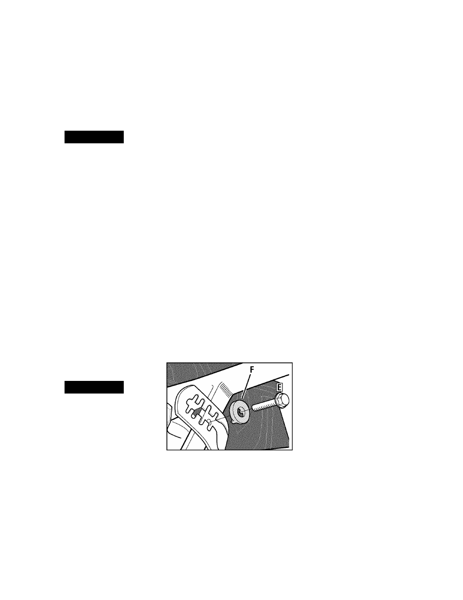
Figure 3-3: Handlebar height adjustment.
1. Stop the engine, wait for all parts to
stop moving and then disconnect the
spark plug wire. Remove the Ignition key
on electric start models.
2.
Loosen the two screws at the lower
ends of the handlebar.
3.
Loosen the height adjustment screw
(E, Figure 3-3) and pull the keyed washer
(F) free of the slots In the curved height
adjustment bracket.
4.
Move the handlebars to the new slot
setting and Insert the raised keys on the
keyed washer Into the slot. Tighten the
height adjustment screw securely.
5.
RetIghten the two screws at the ends
of the handlebar.
ENGtNE CONTROLS
Refer to the engine manufacturer’s Engine
Owner’s Manual (Included In the tiller lit
erature package) to Identify the controls
on your engine. The following two con
trols are used when stopping or starting
the engine.
iWIPORTANT:
The control for stopping
the recoil start engine Is located on the
engine.
ENGINE THROHLE CONTROL LEVER
The Engine Throttle Control Lever (located
on engIne-see Figure 4-1) Is used to reg
ulate the engine speed. On the recoil start
model only. It Is also used to stop the
engine (on the electric start model, the
electric start keyswitch Is used to stop the
engine). The throttle settings are shown
below.
iWIPORTANT:
See “Starting and Stopping
the Engine” In the “Operation” Section for
detailed engine starting and stopping
instructions.
FAST
- Use for most tilling and
cultivating projects.
.SLOW
- Use when idling engine or
when slower tilling and cultivating
speeds are needed.
STOP
- Stops the engine (on
recoil start models only).
ELECTRIC START KEYSWITCH
(MODEL E666M)
The ignition keyswitch on the electric start
model is used to start and stop the
engine. The keyswitch settings are
described below.
IMPORTANT:
See “Starting and Stopping
the Engine” in the “Operation” Section for
detailed instructions.
OFF
- Stops engine.
RUN
- After starting, key returns to run
position.
START
- Starts engine. Release key when
engine starts (avoid cranking engine for
longer than 15 seconds for each attempt)