Generac Power Systems NP Series User Manual
Page 9
Attention! The text in this document has been recognized automatically. To view the original document, you can use the "Original mode".
Section
2
-
Operation
PRIMEPACT 55G and 55LP Recreational Vehicle Generators
OPERATION
фо
2.1
GENERATOR CONTROL PANEL
The following features are mounted on the generator
control panel (Figure 2.1):
♦ 2.1.1 FUEL PRIMER___________________________
Before starting a cold engine (if it has not been start
ed in more than two weeks), you must press this
switch for approximately 10 seconds to bring fuel
from the tank to the fuel pump. This rocker type
switch springs back into its original position when
you release it.
♦ 2.T.2 START/STOP SWITCH____________________
To crank and start the engine, hold this switch in the
START position. Release the switch when the engine
starts. To stop an operating engine, press and hold
the switch in the STOP position until the engine shuts
off. The switch center position is the RUN position.
♦ 2.1.5 15 AMP FUSE____________________________
The fuse protects the engine’s DC control circuit
against electrical overload. If the fuse element has
melted open due to overloading, the engine cannot be
cranked. If you must replace the fuse, use only an
identical 15 amp replacement fuse.
NOTE:
If this generator has been reconnected for dual
voltage AC output (120/240 volts), you can install
line breakers having an amperage rating that is
different than that stated above. The replacement
line breakers consist of two separate breakers with
a connecting piece between the breaker handles
(so that both breakers will operate at the same
time). If the unit is reconnected for dual voltage,
it is no longer RVIA listed.
2.2
OPTIONAL REMOTE
START/STOP PANEL
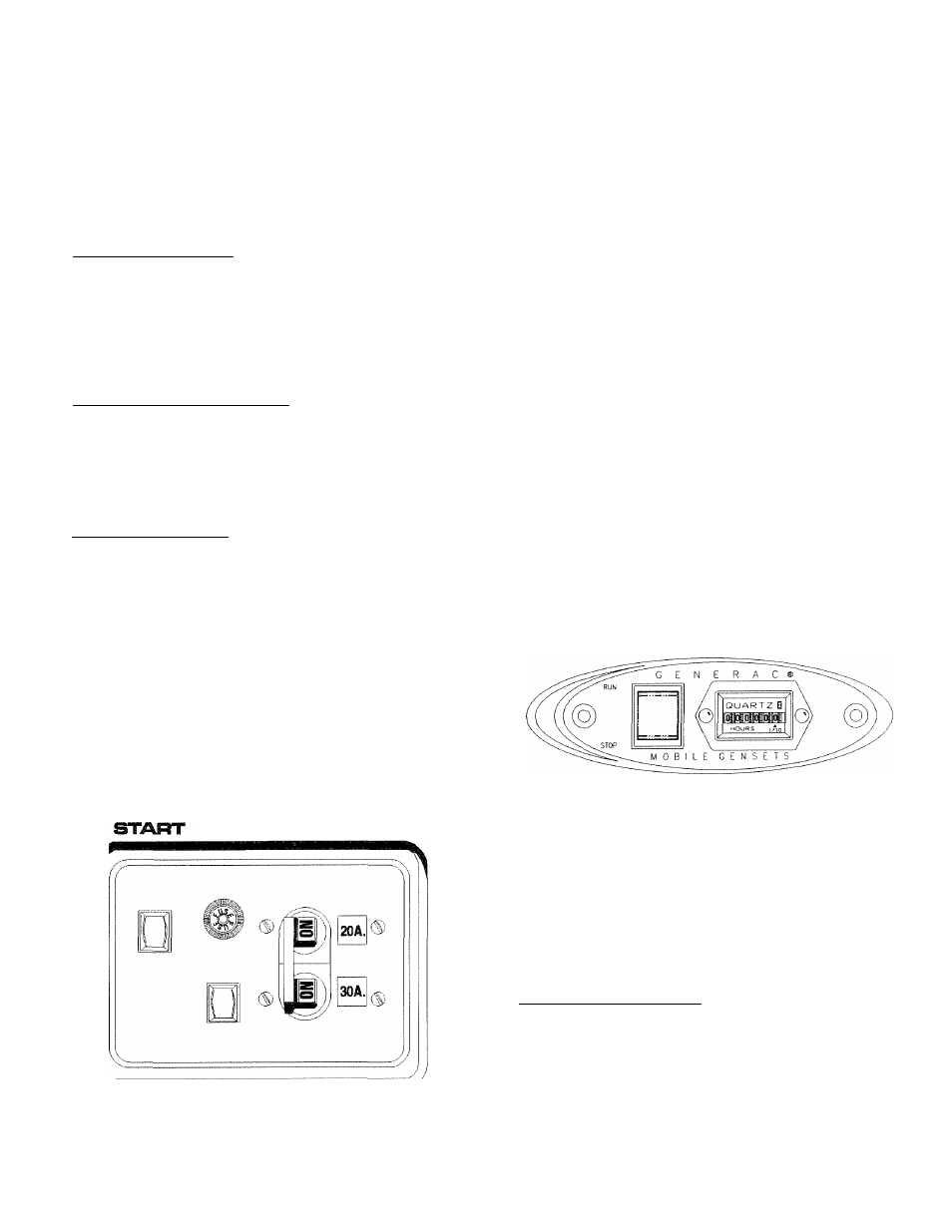
A remote mounted Start/Stop Panel (Figure 2.2) is
available that allows you to start and stop the gener
ator engine conveniently from Inside the vehicle. The
remote panel Includes a Start/Stop switch, hour me
ter, generator run lamp and a wire harness.
Figure 2.2
—
Optional Remote Panel
(Models 004057 and 004184)
♦ 2.1.4 LINE BREAKERS
Protects
generator’s
AC
output
circuit
against
overload,
i.e.,
prevents
unit
from
exceeding
wattage/amperage capacity. This unit has one 20-amp
and one 30-amp breaker.
Figure 2.1 - Typical Control Panel
FUSE
ISA
IVIAII4I
BREAKER
STOP FUEL
PRilVIER
2.3
AUTOIVIATiC CHOKE
This engine is equipped with an automatic choke that
consists of two main components: a choke solenoid
and prechoke.
♦ 2.3.1 CHOKE SOLENOID________________________
During
engine
cranking
(Start/Stop
switch
at
START),
a
solid-state
choke
module
signals
the
choke solenoid to activate and cycle (choke on/choke
off) until the engine starts. The choke solenoid thus
opens and closes the carburetor choke valve only
when the engine is cranking. When the engine starts,
the choke stops cycling.
Generac* Power Systems, Inc.