High temperature shutdown, Field boost, Hour break in period – Generac Power Systems 00916-1 User Manual
Page 11: Duebunueoneid
Attention! The text in this document has been recognized automatically. To view the original document, you can use the "Original mode".
Generac NP-50G Recreational Vehicle Generator
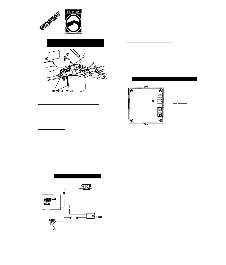
Figure 5 — Switches fdi’ Engine
Safely Shutdown
HIGH TEMPERATURE
SWITCH
LOW OIL PI
■ HIGH TEMPERATURE SHUTDOWN
A high temperature switch (Figure 5) with normally-open (N.O.)
contacts is mounted near the oil filter. If engine temperature
were to exceed about 284°F (lAOX), the switch contacts
close and the engine shuts down.
■ FIELD BOOST_______________________________
The Controller Circuit Board houses a field boost diode and
resistor which are not part of the automatic choke circuit.
These two components are part of a “field boosf circuit (Rgure
6). During engine cranking oniy, a positive DC (battery) volt
age is deiivered through the diode, resistor, brushes and slip
rings, and the generator rotor. Application of this voltage to
the rotor “flashes the field” whenever it is started. Fiashing of
the fieid each time the generator starts makes sure that a suf
ficiently strong magnetic field is available to produce “pick-up”
voltage in the stator windings.
Figure 6 — Field Boost Circuit
CUISESI1Q
BUBIU
■ OVERVOLTAGE PROTEaiON________________
A solid state voltage regulator (Figure 7) controis the gener
ator's AC output voitage. This regulator suppiies an excitation
current to the rotor. By regulating the rotor’s excitation cur
rent, the strength of its magnetic fieid is reguiated and, in turn,
the voltage delivered to connected electrical loads is con-
trolied. When the AC frequency is 60 Hz, voltage is reguiated
at 120 volts (voltage-to-frequency ratio is 2-to-1).
Figure 7 — Solid State Voltage Regulator
I’
d
-»»»
TBum
10 MIMI __________
i==)^iH-^(inEn cnnam
—i-nmiiiifiii
ExanmoiiiinK
dUEBunueonEiD
The voltage regulator also incorporates a “voitage surge pro
tection circuit.” This circuit prevents troublesome surges in the
generator AC output voltage. Voltage surge is a common cause
of damage to electronic equipment.
■ 25-HOUR BREAK IN PERIOD
The first 25 hours of operation is the break-in period for the
generator. Properly breaking in the generator is essential to
minimize fuel consumption and provide maximum engine per
formance. During this 25-hour break in period, foiiow this
procedure:
• Run the unit at varying electrical loads, to help seat engine
piston rings properiy.
• Check engine oii levei frequently. Add oil if needed. It is
normal for the generator engine to consume more oil than
is normai until the piston rings have properly seated.
• For the 75-hour operation foilowing the break in period,
avoid light electrical loads. Load the generator at 50% (or
more) of its rated wattage capacity. Repeated iight loads
during these 75 hours can cause improper seating of engine
piston rings, resulting in blowby and high oii consumption.
• After operating the unit for 25 hours, complete the tasks rec
ommended under “25-Hour Check Up."
R e c r e a t i o n a l V e h i c l e G e n e r a t o r
11