Assembly – Poulan 210 User Manual
Page 7
Attention! The text in this document has been recognized automatically. To view the original document, you can use the "Original mode".
ASSEMBLY
A.
GETTING READY
l.READ YOUR OPERATOR’S MANUAL CARE
FULLY
Your Operator's Manual has been developed to help
you prepare your saw for use and to understand its
safe operation. It is important that you read your
manual completely to become familiar with the unit
before you begin assembly or attempt operation. Your
POULAN PRO dealer is available to show you how
to operate your saw. Be sure to ask for assistance.
HAVE THE FOLLOWING AVAILABLE
a. Protective gloves.
b. Approved, marked fuel container.
c. One gallon regular unleaded gasoline.
d. 2 cycle, air-cooled engine oil (See the “Fueling
Your Engine’’ section).
e. Bar and Chain Oil (See the “Bar and Chain Oil”
section).
f. Scrench.
I
B.
ATTACHING THE BAR AND CHAIN
•
Your saw is equipped with a Reduced-Kickback
Bar and a Low-Kickback Chain.
•
Always use the Reduced-Kickback Guide Bar and
Low-Kickback Chain specified for your chain saw
model when replacing these parts. See the “Speci
fications” section.
A
WARNING
Do not start engine without guide bar and chain com
pletely assembled. Otherwise, the clutch can come off
and cause serious injury.
[CAUTION; I Wear protective gloves when handling
or operating your saw; the chain is sharp and can cut
you even when it is not moving!
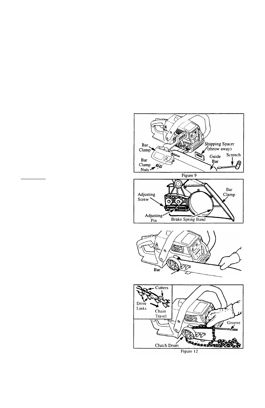
1. Remove the following parts as shown in Figure 9,
using the scrench provided with the unit.
a. Bar clamp nuts.
b. Bar clamp.
c. Shipping spacer (throw away).
2. Turn the adjusting screw (Figures 10 & 13) counter
clockwise to move the adjusting pin (Figure 10)
almost as far as it will go to the rear.
3. Mount the guide bar with the slotted end over the bar
studs. Figure 11.
4. Hold the chain with the cutters facing as shown in
Figure 12 (in.set).
5. Place the chain over and behind the clutch drum and
onto the sprocket. Figure 12.
6. Slide the guide bar toward the rear of the saw as far
as possible.
7. Fit the bottom of the drive links between the teeth in
the sprocket behind the clutch drum.
8. Start at the top of the bar and fit chain drive links into
the groove around the guide bar. Figure 12.
9. Pull the guide bar forward until the chain is snug into
the guide bar groove.
10.
Verify that the adjusting pin is in the rearmost posi
tion. Hold the guide bar against the saw frame and
install the bar clamp. Make sure that the adjusting pin
is positioned in the small hole in the guide bar.
I I .Make sure the chain brake assembly actuating lever is
jn the.'di.seagaged” position to allow the brake band
to fit over the clutch drum. To disengage lever, pull it
toward the rear of the brake assembly. Figure 5.
12.Install the bar clamp unit, making sure the brake
spring band is over the clutch drum. Tighten nuts fin
ger tight only.
13.Proceed to the “Chain Tension” section.
Guide
Mounting Bolts