Assembly, Figure 1, Tools required – MTD 242-595A User Manual
Page 4
Attention! The text in this document has been recognized automatically. To view the original document, you can use the "Original mode".
ASSEMBLY
A--- ►
;
mämttmm
B—*
f-
c—*
c
r*w
n—► *"
ft
%
-im
F-
G-
FIGURE 1
TOOLS REQUIRED
(1) Adjustable wrench or 3/4" open end or bov^
wrench
(2) 7/16" open end or box wrench
(1) 9/16" open end or box wrench
■CONTENTS OF HARDWARE PACK
(See figure 1)
A
(3)
Shoulder Bolts 3/8-16 Thread
B
(3)
Belleville Washers
C
(3)
Lock Washers
D
(3)
Hex Nuts 3/8-16 Thread
E
(2)
Hex Bolts 1/4-20 x 1 1/4" Long
F
(6)
Lock Washers 1/4" I.D.
G
(6)
Hex Nuts 1/4-20 Thread
H
(1)
Compression Spring
1
(4)
Carriage Bolts 1/4-20 x 1 1/4" Long
J
(2)
Cotter Pins
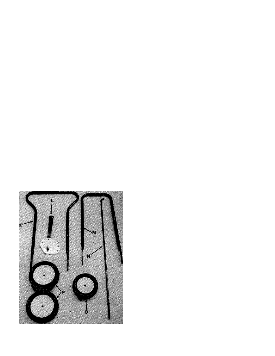
LOOSE PARTS IN CARTON
(See figure 2)
K
(1)
Upper Handle
L
(1)
Preassembled Clutch 1
M
(1)
Lower Handle
N
(1)
Clutch Rod
0
(1)
Front Wheel 6"
Dia.
P
(2)
Rear Wheels 7" Dia.
FIGURE 2
Your new edger is shipped preassembled with the^
exception of the handle, rear wheels and front whr
1. Remove the edger and all parts from the cartoti.
Make certain that all loose parts and literature
are removed from carton before carton is dis-
carded.