Assembly, Instructions, Loose parts in carton (see figure 2.) – MTD 243-685A User Manual
Page 4: Assembly instructions
Attention! The text in this document has been recognized automatically. To view the original document, you can use the "Original mode".
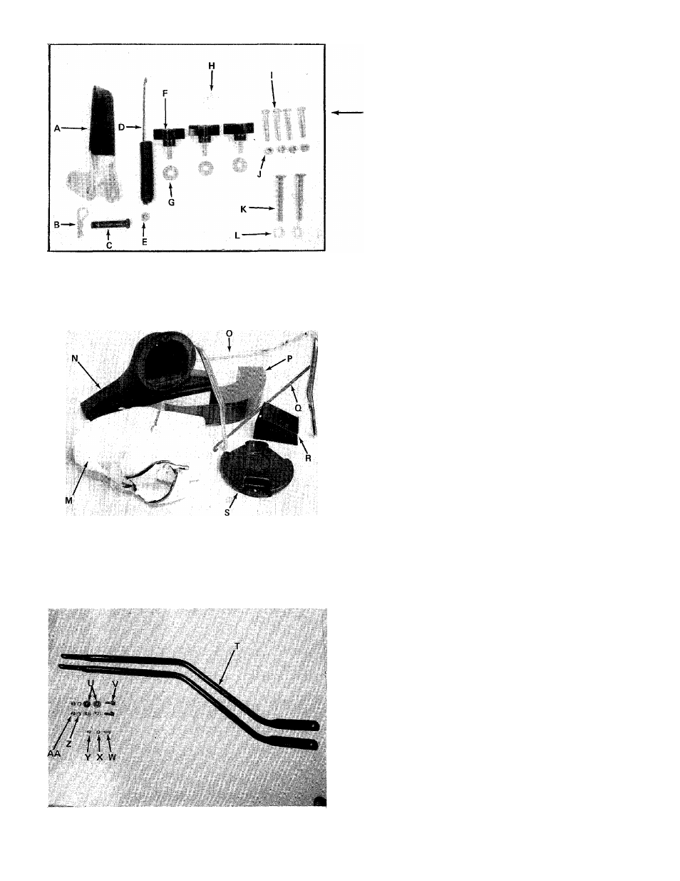
FIGURE 1.
ASSEMBLY
INSTRUCTIONS
CONTENTS OF HARDWARE PACK
(See Figure 1.)
A
(1)
Clutch Grip Assembly*
B
(1)
Hair Pin Cotter*
C
(1)
Clevis Pin*
D
(1)
Extension Spring*
E
(1)
Lock Nut 1/4-20 Thread*
F
(3)
Hand Knobs
G
(3)
Belleville Washers
H
(1)
Heavy Flat Washer
1
(4)
Hex Bolts 1/4-20 x 1.75" Long
J
(4)
Hex Lock Nuts 1/4-20 Thread
K
(2)
Stud Pins
L
(2)
(1)
Push-on Speed Nuts
Hex Jam Nut 1/4-20 Thread* (Not Shown)
LOOSE PARTS IN CARTON
(See Figure 2.)
N
0
P
Q
R
S
(
1
)
(
1
)
(
1
)
(
1
)
(
1
)
(
1
)
(
1
)
Bag
Nozzle
Upper Handle
Air Duct Assembly
Clutch Rod*
Directional
Discharge
Assembly
Impeller Guard
*Self-Propelled Models Only.
FIGURE 2.
TOW BAR KIT - Standard with push models. Optional
(See figure 3.) with self-propelled models.
T
(2)
Tow Bar Halves
U
(4)
Shoulder Spacers
V
(2)
Hex Bolts 5/16-1
8 X
1.00" Long
w
(1)
Truss Machine Screw 1/4-20 x .75'
X
(1)
Lock Washer 1/4" I.D.
Y
(1)
Hex Nut 1/4-20 Thread
Z
(2)
Lock Washers 5/16" I.D.
AA
(2)
Hex Nut 5/16-18 Thread
FIG U R E S .