To adjust motion control lever (see fig. 25), To adjust steering wheel alignment, Front wheel toe-in/camber – Poulan 157469 User Manual
Page 23: I remove wheel for repa, See fia. 27), See fig. 25), Transmission removayreplacement, See fia
Attention! The text in this document has been recognized automatically. To view the original document, you can use the "Original mode".
r< ;
1
I Â i - ÎÎ ii> ? .
1
, ?v'r ii r
1
■'
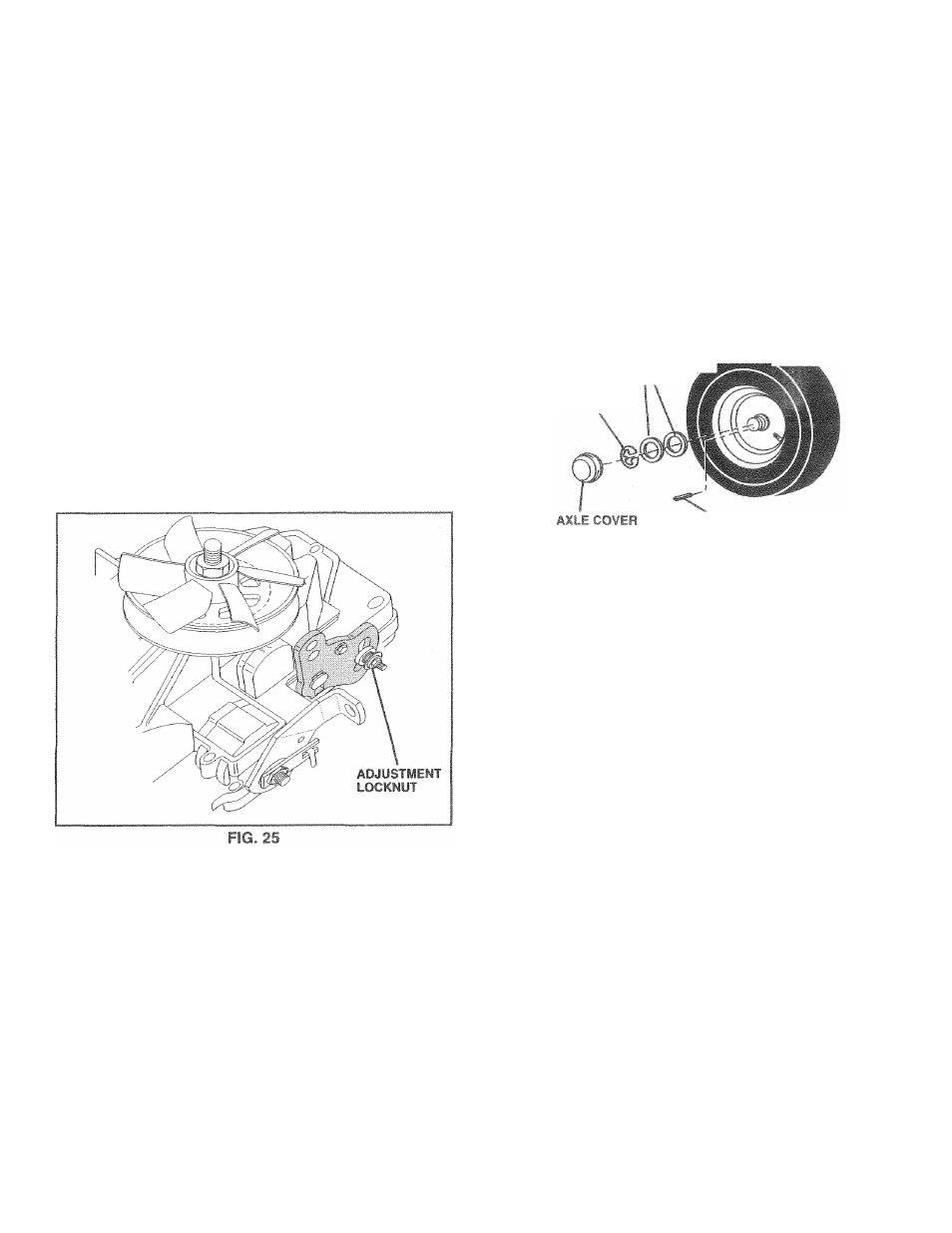
TO ADJUST MOTION CONTROL LEVER
(See
Fig. 25)
F ; ;i I 11 .-I
5 * * K ‘
f > i ( ll ! < . 'I
adjustmsnt should not be necessary.
If for any reason the motion control lever will not hold its
p.,' It <1(1 v.fiil' -ti • i-U !,i,-o >i it hr
P ’ >
,.d,i i< '' u iO>
fi'ktiui l-diK Im J e t i i
l
' i
* Pjd h i r f O i ^*r- t e "”i
!>i».Vi‘ li ¡> .MtJi.r 5 , t h I S « ' ;
iinition Kf-d t', ( ) s h ti{.sitii»n Olid onQiqe raiK'nn
brake.
r tii1|U?t trioiioii { •iiliol !e/^i i-y iioh'rriiiiy adju-ii-'cnt
lc)cl NOTE*: I t tor ««ly rc:.''.n;i inr fTfO-rt lo rno'f tN 'iic coni.ol l e / e i h e n ' m t ' . too ¿.te-cii/H. iliL abovr adjustment profcdort by loo.crtinq lo^.ftiui i/4to i/r lurn TRANSMISSiON REMOVAyREPLACEMENT Should your transnii'‘‘'ii r, requKS removal ter cen/ice or TO ADJUST STEERING WHEEL ALiGNMENT If steering wheel crossbars are not horizontal (left to right) when wheels are positioned straight forward, remove steer FRONT WHEEL TOE-IN/CAMBER The front wheel toe-in and camber are not adjustable on I REMOVE WHEEL FOR REPA sa Fin 5f5| .rC r ly« ifcw| Block up axle securely. wheel removal (rear wheel contains a "i n-",l ,"tr ''-k (ir«l > ,;|n. f < II. -nd imr,rT:r|unw d, Hopio' 0 wi'.m.r m.u 1 ! “p i«.ir,.rii!iu L I , « . • f ! « i y 1/!« RLjrnyt. ->*; '■f". I washebs ftfc imhmt vi ^ RING ' sioaiic rear wheel hi CQliAaF Kr ,1 (REAR WHtCL ONLY) (See Fia. 2 7 ) 'i CAUTION Lead-as id battetiec gtoei- -,r«ci smokiBa rr.ateials îr.-m terie<. Alway wî 3 f p-c.iction when s cui«/ ■ 1 your battery i if n 1 1 -fr rt ttfo etajifv li AiMiW be rcfh..rged •!‘jiimpr ijoie*-' u i d kv meirieiicy 't .itr.g rdkiv thw pr ..-‘''uv IMPcRlANI uiiP7 A,, fll iL. I it n U l i . i / i / vCL. l'L<.An«/fc: GN'iUiT'ki f> r t f ' d L W T H r r 'tHI> LF Ml' .■ Al r rf I ' O', i |!f ( ' i i v r wrtOUtJDFD 3/MtM I G M f i M'm .hm .op h A T l F P f T > } T A R T m r H t ^ /FHli ‘ in A i r/TH !i MF[ f i py rC • Connect each end of the RED cable to the POSITIVE • Connect one end of the BLACK cable to the NEGA- ! R'E (I 'rniin r! m itiiiy t h'•r(F i b tr » • Connect the other end of the BLACK cable to good TO REMOVE CABLES, REVERSE ORDER - LI Alt' u.’bLfi irf'.i h< < j'Jffi. ♦ iri'A' idlli h' I * , ri i-t l I"') « b' ‘b I ife •
Road toct tractor after adjusiment ano repeac <>.'uf cdiiie p
necessary
replacement, it shiuila be purged after reinstaliation and
before operating the tfictcr. cree ‘PURGE TR'^NSMtS-
SION” in tfie Opfatrjri ? f ction of inis rrunual.
ing wheel and reassemble per instructions in the Assembly
section of this manual.
your tractor. !f damage has occurred to affect the front
wheel toe-in or caiïibei, cotilaci your nearest authorized
Remove axle cover, retaining ring and i
not lose).
Repair tire and reassemble.
aie explosive gases. IsfetpiparM flame
{+) ttirnm ¡I or r A I r«itti. frhrvi a« ' ' v on
a tail
'“HA y. ¡iRuilRb w .iV-ruii
charged battery.