Throttle-assemble as shown in figure 6, Caution, Handle panel – MTD 213-380 User Manual
Page 3: Conduit, Figure 6. throttle control, Check list before operation
Attention! The text in this document has been recognized automatically. To view the original document, you can use the "Original mode".
CONTROL ROD
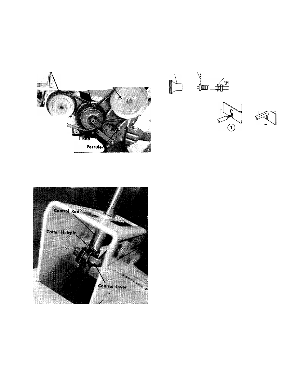
THROTTLE-Assemble as shown in figure 6.
Screw the control rod into the ferrule until it extends
through the ferrule % of an inch. See figure 4.
Engiiis|T»uHey
«a. '
j-J"- ■ Chain Case'^Ej^HI
VanSBle Speed Pulley
Pulley
Control
FIGURE 4. FERRULE ADJUSTMENT
Place the bent end into the control handle as shown
in figure 5 and fasten with a cotter hairpin.
FIGURE 5. CONTROL ROD
CAUTION
Knob
Handle Panel
Spring Lockwasher
ex Nut
Conduit
©
FIGURE 6. THROTTLE CONTROL
CHECK LIST BEFORE OPERATION
1. Check tiller tines for proper installation. With throt
tle control lever set on STOP position and the con
trol lever set in No. 1 position, slowly crank engine
to determine direction of tine rotation. Be sure all
tines are mounted so the sharpened edges enter
the soil first.
2. Check all nuts and bolts for proper tightness. This
is especially important during the initial operation
period. Make the same check periodically there
after.
3. Check throttle control for proper setting. Move
throttle control knob to STOP position. Move lever,
to which control wire is fastened at engine, to
CLOSE position and retighten screw to secure throt
tle control wire assembly.
4.
Check fuel tank. Clean, fresh, regular gasoline
should be used at all times.
5. Check engine crankcase for proper oil level. The
engine is shipped without oil in the crankcase. Be
sure crankcase is FULL.
STARTING YOUR TILLER
With the spark plug wire disconnected
and grounded, place the control lever in
NEUTRAL and pull the recoil starter sev
eral times. THE TINES SHOULD NOT
TURN. If they do, screw the control rod
into the ferrule several more turns as
shown in figure 4.
1. Be sure clutch control handle is in NEUTRAL posi
tion.
2. Move throttle control lever to STOP position.
3. Move choke lever, located at the engine, to CHOKE
position. Refer to your engine manual.