Wheels, Depth bar, Lock pin – MTD 213-380 User Manual
Page 2
Attention! The text in this document has been recognized automatically. To view the original document, you can use the "Original mode".
ASSEMBLY
HANDLE ASSEMBLY
Your rotary tiller is shipped complete in a single car
ton. The wheels, handle, controls and depth bar are
to be assembled. This is done in the manner described
below.
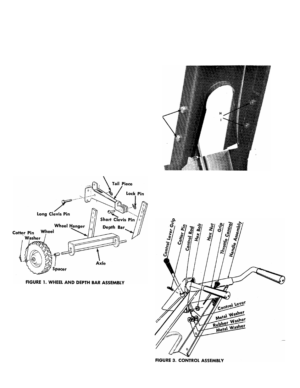
WHEELS
Assemble the axle to the wheel hanger. Place the
spacer over the axle and assemble the wheel, with a
washer on both sides of the wheel, to the axle. See
figure 1. Secure each wheel with a cotter pin.
Place the wheel hanger inside the tailpiece and secure
with the long clevis pin and lock pin. See figure 1.
DEPTH BAR
Assemble the handle to the handle brackets with four
cap screws, lockwashers and hex nuts as shown in
figure 2.
Assemble the depth bar to the tail piece using the
short clevis pin and lock pin. See figure 1.
Lock Pin
FIGURE 2. HANDLE ASSEMBLY
CONTROL LEVER
Place clutch control lever through handle panel. Se
cure in place with hex bolt, flat washers, rubber wash
er and hex nut. See figure 3.