Shield ~ ficnre 4, Shield ~ ficnre 4 a, Figures – Poulan 1400T User Manual
Page 8
Attention! The text in this document has been recognized automatically. To view the original document, you can use the "Original mode".
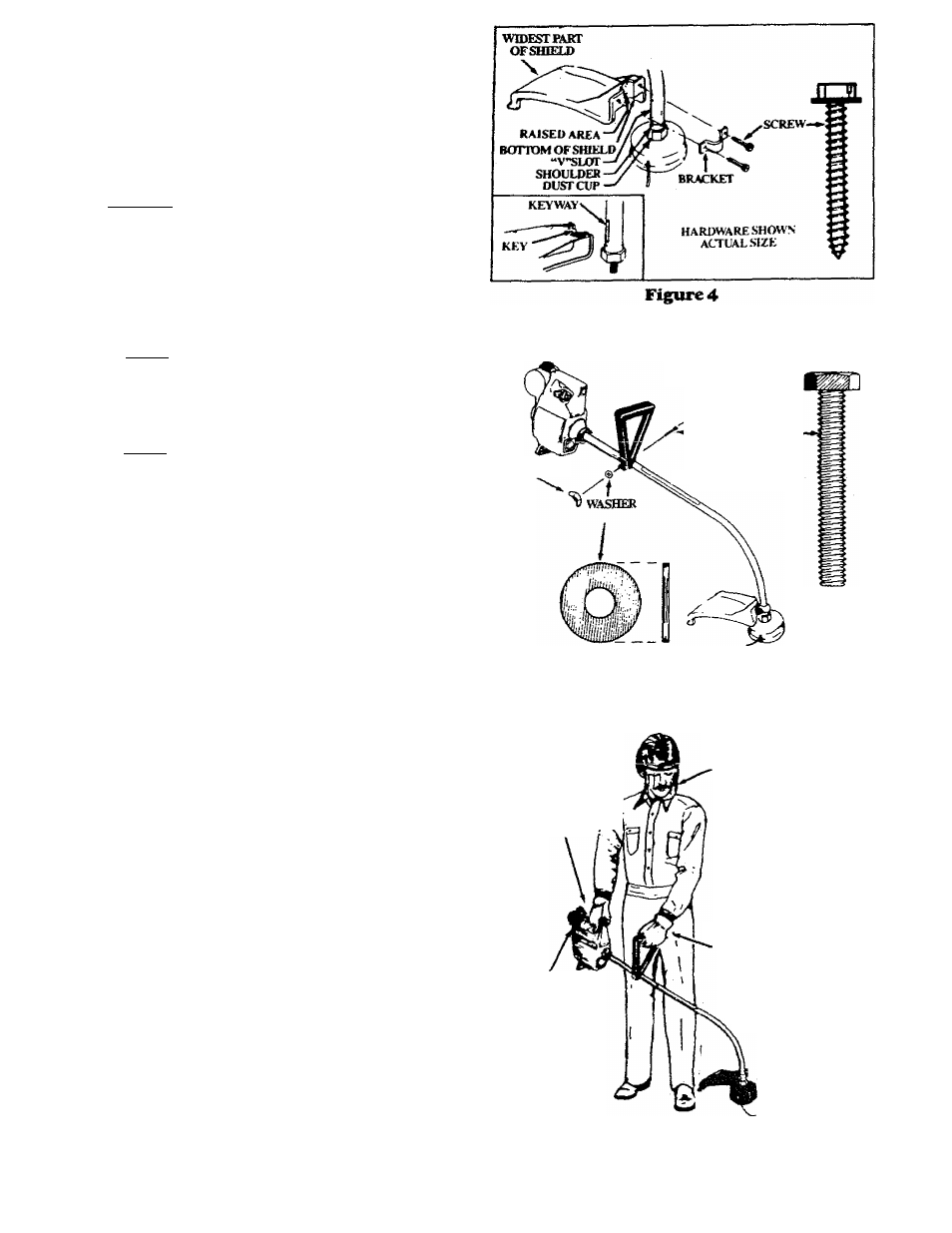
3. SHIELD ~ Ficnre 4
A
warning
F^ure
to
instaU
thesluddmtlie
position
showninflgure
4 and 5 can result in serious iiyury to the operator. The
iei^th of the shield must be aligned with the length of the
driveshaft housing. Direct the widest part of the shield
toward the engine.
iCilJPTloi^ The Line Limitor Is sharp and can
cut you.
a. Match the Key (Raised area) on the Shield with the
Keyw^ (“V” slot) on the Drive Shaft Housing.
Figure 4(1 nset),
b. Rest the bottom of the Shield on top of the shoulder
located on the Drive Shaft Housing above the Dust
Cup.
NOTE: The bottom of the Shield must rest on top
of the shoulder of the Drive Shaft Housing.
c. Install the Bracket and Screws as shown in Figure
4.
d.
Tighten the Screws evenly and securely with a
wrench,
NOTE:
A
small space m^ be left between the
Bracket and the Shield when hardware is fully
tightened.
4. ASSiST HANIiLE ^Figure 5
a. Hold the Assist Handle and with the hollow side fac
ing the Engine so it is aligned between the Engine and
the Safety Label on the Drive Shaft Housing.
Figure 5.
b. Firmly push the Assist Handle over the Drive Shaft
Housing. Figures.
c. Install the Bolt in the side of the Assist Handle with
the hex opening.
d. Install the Washer and Wing Nut. Figure 5.
e. Tighten the Wing Nut by hand o/z/v.
5,OPERA*mi€Pi>SiTI©N — FifKTe6
a.
Before starting the Engine,
stand as shown in
Figure 6 and check for the following:
1) , Left arm fully extended, hand holding Assist
Handle.
2) . Right arm slightly bent, hand holding the Rear
Handle, and fingers on Throttle Trigger.
3) . Rear Handle below waist level.
4) . Weight of tool evenly distributed between arms.
5) . Without operator bending, the Trimmer Head is
near and parallel to the ground and easily con
tacts the material to be cut.
b.
Adjust the Assist Handle
up or down the Drive
Shaft Housing (bur above the Safety Label) to a
comfortable position,
1) . Loosen the WingNut by hand, adjust the Assist
Handle. Retighten Wng Nut by hand only.
2) . Rotate the Assist Handle from leftto right if it is
necessary to tilt the angle of the Trimmer Head
when cutting a large, sloped area such as a ditch
bank.
HARimARt: SHOW N
ACTlAi.SlZi-:
BOLT-
WINGNUT
.^SAFETY LABELS
Figures
RIGHT AKM
SLIGHTI.Y BENT.
HAND HOLDING REAR
HANDLE, FINGERS ON
THROTTLE
r W
TRIGGER
REAR HANDLE
BELOW
WAIST LEVEL
SAFEn’ FACE SHIELD
LEFT ARM EXTENDED.
HAND HOLDING
A.SS1ST HANDLE
TRIMMER HEAD IS
NEAR THE GROUND AND
EASILY CONLWrrS
MATERIAL TO BE CUT
Figured