D. line replacement, Figuréis – Poulan 1400T User Manual
Page 14
Attention! The text in this document has been recognized automatically. To view the original document, you can use the "Original mode".
D. LINE REPLACEMENT
• For proper Une feed:
— Use only
genuine
Weed Eater®
pre-wound spools
and
bulk
line. Use of other spools or line can result in
excessive breakage, line welding, and improper line
feed.
—
Pre-wound spools offer the most convenient
method for replacing line
as well as optimum per
formance.
• Always dean dirt and debris from the spool and hub
when performing any type maintenance.
JLInstallIng Spool w/Line
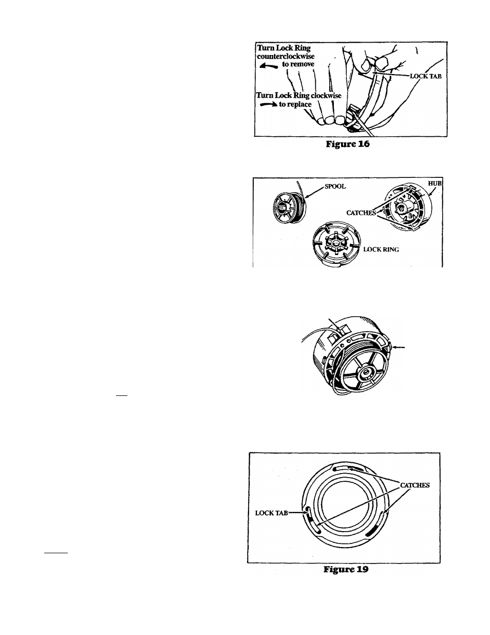
a. Hold the Trimmer Head as shown in Figure 16. Press
the Lock Tab and turn Cover counterclockwise
b. Remove the Lock Ring and Spool. Figure 17,
c. Clean dirt and debris from all parts. Inspect all Trim
mer Head parts for damage. Replace damaged parts.
A
WARNING
Trimmer head parts that are chipped, cracked, or
damaged in any way can fly apart and cause serious
injury. Do not use. Replace damaged parts before
using the tool.
d. Insert the end of the Line in the Line Exit Hole as shown
in Figure 18. Place Spool in Hub.Make sure the Trim
mer Line is not caught between the rim of the Spool and
the Hub.
e. Align the Lock Ring over the three Catches on the
Hub. Push the Lock Ring down on the Hub and turn
clockwise ^ , Figures 16 and 17.
Check to maj^ sure ^11 three Catches and the Lock
Tab are properly festened (as shown in Figure 19)
ly attempting to turn the Lock Ring counterclock
wise i*—^ and pulling on it. Then test the Lock Ring
by trying to turn it counterclockwise A—^ ,
Figure 17
LINE EXIT HOLE
LOCK TAB
Figuréis
AwABNme
AH three catches must he fastened and the lock tab
latched on to the lock ring. If installed incorrectly, the
lock lii)^ can fly off and become a dangerous m^sile.
g. Pull on the Line to change the Spool from the locked
position to the operating position. Figure 20.
h. Obtain correct line length by pressing Tap Button and
pulling on the Line again.
NOTE: Each time the Tap Button is pressed, approx-
imately 2 inches of line can be pulled from the Trim
mer Head. Figure 20.
14