L mowi and 5), Mower levelness, Smon of all – Poulan 159515 User Manual
Page 9
Attention! The text in this document has been recognized automatically. To view the original document, you can use the "Original mode".
Figs
.L MOWi
and 5)
factor is on
raised with
E BELT (See
fhrr
3ce a
it 'hi
iki
lower suspension
.cn'rol.
Engage
park-
c//ay ba
curing anth
!oit oido oi
i/ay
bar and
belts,
sower deck.
•
cut and remove
Swing anti
•
Slide mower under tractor with discharge guard to right
side of tractor.
iMPORTANT; CHECK BELT FOR
P R O F ' E R
ROUTING ¡N
ALL MOWER PULLEY GROOVES, INSTALL BELT INTO
ENGINE PULLEY GROOVE,
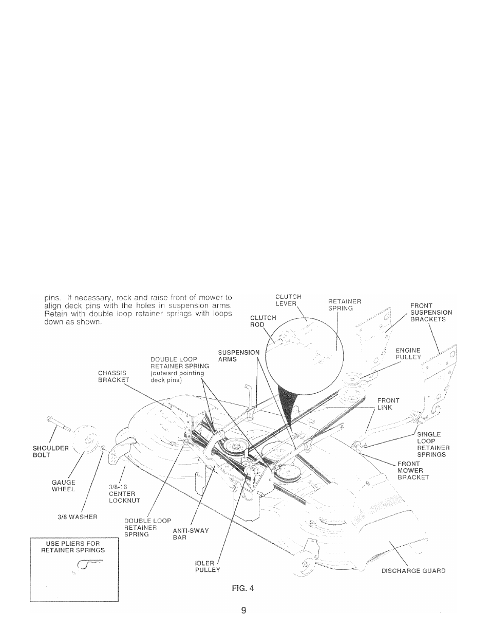
» Install one front linK in top hole of the L.H. front mower
bracket and L.H, front suspension bracket. Retain with
two single loop retainer springs as shown,
•
Install second front link in R.H. front suspension bracket
and retain with single loop retainer spring as shown.
•
Slide right side of mower back and install link in top hole
of
R.H.
front m,ower bracket. Retain
with single
loop
retainer spring as shown,
•
Turn height adjustment knob counterclockwise until it
stops.
» Lower miower linkage with attachment iift control.
Place the suspension arms on outward pointing deck
Connect anti-sway bar to chassis bracket under left
footrest and retain with double loop retainer spring.
Install clutch rod in clutch lever. Secure with retainer
spring.
Turn height
clockwise to remove
slack f.rom n
Raise deck i
culder
ighten
■as shown
СНЕС
MOWER LEVELNESS
F
oidc
.. I
1 iiiv I cuiis n v ' V i . r iiouki po piopc ily leveled.
Stt ¡0 L.L /
l
.
l
_
MOWEn HuUbIMG m
[he
Cervice and
Adjustmients section of this manual.
ClltfO
БГ* 0
SmON OF ALL
See the figures that are s
dm I-
I "f I I I If
A
* J u
h
< (
I i >
к
U P t i ( I n 1 V
r n Ю
■ive
lanu
ilacing motion,
mower
5 in the Service and
Gerify that the belts are