To replace mower blade drive belt (see fig. 24), To adjust brake (see fig. 25) – Poulan 159515 User Manual
Page 23
Attention! The text in this document has been recognized automatically. To view the original document, you can use the "Original mode".
rotate
MOWER DHE
k6€3De
INÌ
Idle
WLATION
v1ake sure
)wn.
» » i
1
«
4 i
! ■ % I l l
r s
.ee
I h s t
Ihcy
• Reinst.
AND C
all
mower
to t
)RIVE BELT”
ractor
in the
/ S i “ [ . - M , " .
Assembly sec
1 M f ' W F i '
lion
j
I
i
I
m s
Fig, 23) -
;
in both
belt
rnanua
®
Beasse
MOW E
amble mower
tR DRIVE BEL
drive belt (See
“TO
lis section of tl"
REPLACE
us manual).
Install new belt onto engine pulley.
Hoii Pelt into upper groove
ot
l
,
h
. manarei pulley.
Carefully check belt routing making sure belt Is in the
grooves correctly and inside belt keepers.
FIG. 23
TO REPLACE MOWER BLADE DRiVE BELT
(See Fig. 24)
Park the tractor on level surface. Engage parking brake.
•
Remove mowerdrive belt (See “TO REPLACE MOWER
DRIVE BELT" in this section of this manual).
•
Remove mower (See “TO REMOVE MOWER” in this
section of this manual).
•
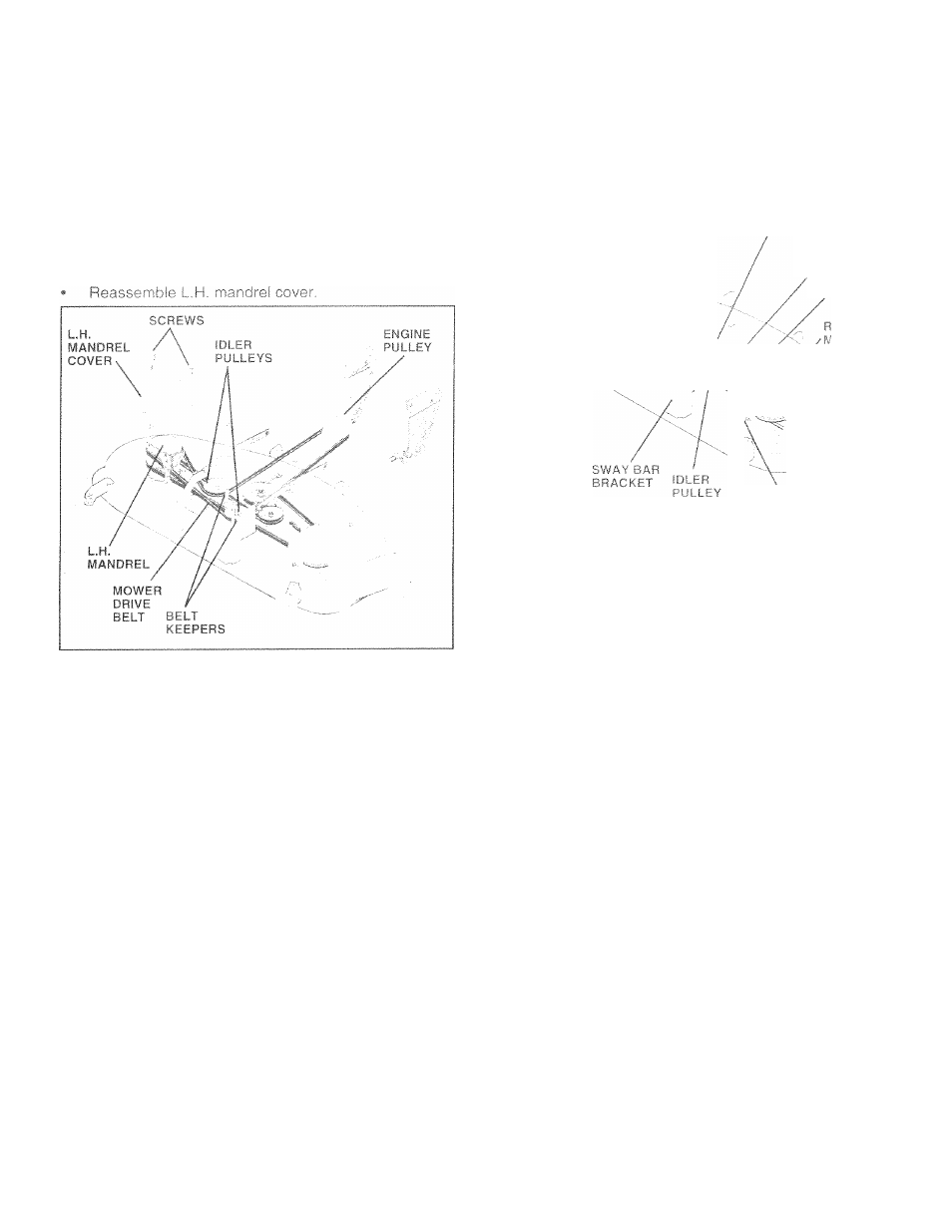
Remove four screws from R.H. mandrel cover and
remove cover.
•
Carefully roll belt off R.H. mandrel pulley.
•
Remove belt from center mandrel pulley, idler pulley,
and L.H. mandrel pulley.
•
Remove any dirt or grass which may have accumu
lated around
mandrels
and entire upper deck surface.
•
Check secondary idler arm and idler to see that they
rotate freely.
•
Be sure
spring
is
hooked in
secondary
idler arm
and
sway-bar bracket.
•
Install new belt in lower groove of L.H. mandrel pulley,
idler pulley, and center mandrel pulley as shown.
•
Roll belt over R.H, mandrel pulley. Make sure belt is in
all grooves properly.
•
Reconnect secondary clutch rod to pivot rod with
retainer spring.
•
Reinstall R.H. mandrel cover.
MOWER
L.H.
MANDREL DRtVEt
BELT
ivf ^ L..Ì 1 L.
SEECONDARY
IDLER
ARM
SPRING
.H.
ANDREL
OVER
SCREW
FIG.
24
TO ADJUST BRAKE (See Fig. 25)
Your
tractor is
equipped
with an adjustable
brake
system
which is mounted on
the
side of
the
transaxle.
If tractor
requires
more than six (6) feet stopping distance
at high
speed
in
highest gear, then braKe
must be adjusted.
•
Depress clutch/brake pedal and engage
parking brake.
» Measure distance between brake operating
arm and
nut "A" on brake rod.
•
If distance is other than 1 -3/4“. loosen jam nut and turn
nut "A" until distance becomes 1-3/4". Retighten jam
nut against nut “A".
•
Road test tractorfor proper stopping distance as stated
above. Readjust if necessary, if stopping distance is
still greater than six (6) feet in highest gear, further
maintenance is necessary. Contact your nearest au
thorized service
center/department.
WITH PARKING BRAKE “ENGAGED"
NUT “A”
/
-JAM
NUT
\
OPERATING
ARM
DO NOT TOUCH THIS NUT, IF FURTHER
BRAKE ADJUSTMENT IS NECESSARY
CONTACT YOUR NEAREST AUTHORIZED
SERVICE CENTER/DEPARTMENT
FIG. 25
23