Fill fuel tank, A warning, To install the edger attachment – Troy-Bilt 12097 User Manual
Page 6
Attention! The text in this document has been recognized automatically. To view the original document, you can use the "Original mode".
Section 2: Assembly
Chart 1: FUEL MIXTURE
(Mixture Ratio is 24 parts gasoline to
1 part two-cycle oil)
U.S. Gas
U.S. Oil
1 Gal.
5 oz.
2 Gal.
11 oz.
Metric Petrol
Metric Oil
4 liters
167 ml
8 liters
333 ml
4. Do not mix fuel directly in engine iuel
tank. Always use a clean, safety-ap
proved fuel container.
• To Mix:
A. Fill a clean, approved container one
quarter full with recommended gaso
line.
B. Add recommended amount of oil per
Chart 1: FUEL MIXTURE.
C. Screw cap on container and shake
vigorously. Then unscrew cap and
fill container with gasoline per
Chart 1: FUEL MIXTURE. Screw on
cap and shake again. Once mixed,
oil and gasoline will not separate.
Fill Fuel Tank:
1. Engine must be cool. Clean area
around fuel tank cap and remove cap.
Insert a clean funnel into the fuel tank.
2. Slowly pour gasoline/oil mixture into
fuel tank. Fill tank no higher than 1/2“
from top of tank to allow for gasoline ex
pansion. Install fuel cap and clean up any
fuel spills.
A
WARNING
Contact
with
rotating
tines
or
other
moving parts can cause serious per
sonal injury.
Before
installing
or
removing
attach
ments, or adjusting or servicing the ma
chine, stop the engine, let all moving
parts come to a complete stop, discon
nect the spark plug wire and move the
wire away from the spark plug.
STEP 4: To Make Borders and Edges,
Install the Edger Attachment
To create borders or edges near walks,
driveways, flower beds, etc., you must
remove the four tine sections and install
the Edger Attachment (this attachment
was supplied with the unit - see Page 5).
To Install the Edger Attachment:
1. Gather together the following parts
(see Figure 4): (A) Border/Edger Tine; (B)
Long Bushing; (C) Border/Edger Wheel
and (D) Short Bushing.
2. Prop the machine carefully on the front
of the tubular carrying handle. The work
surface should be firm and flat. NOTE:
Usually the Border/Edger Tine is mounted
on the right-side of the unit for right-
handed persons, and on the left-side of
the unit for left-handed persons.
3. Flip open the ring on the two ring lock
pins (E, Figures 3 and 4) and remove the
ring lock pin on each tine shaft.
IMPORTANT: The ring lock pin is under
spring tension - use care when removing
or replacing the ring lock pin.
4. It is important for proper tilling perfor
mance that the tine sections be later rein
stalled in their original positions. Mark
the position of each tine section (Left-
Outer, Left-Inner, etc.) before removing
them. Refer to Figures 3 and 9 for tine
position information. See also
Tine Re
moval and Installation
in Section 5.
5. Install the short bushing (D, Figure 4)
on the right-hand or left-hand tine shaft.
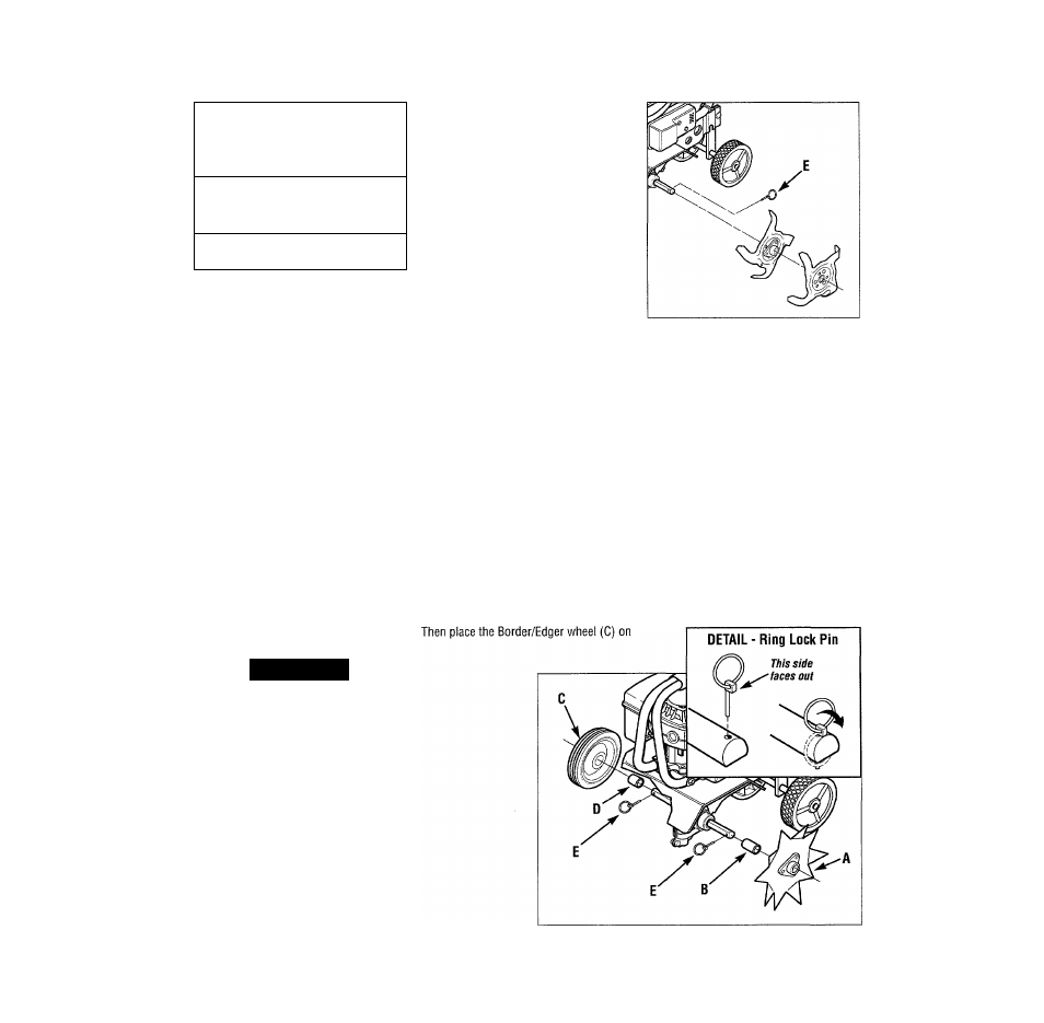
Figure 3: Remove ring lock pins and tines
from both sides of the tine shaft. Keep left
and right-side tines separated and marked
for easier reinstallation.
the same shaft - the wheel hub should
face toward the tiller. Insert the ring lock
pin through the rounded side of the tine
shaft and snap the ring down over the
shaft (see
DETAIL - Ring Lock Pin,
Figure 4).
6
.
Slide the long bushing (B) on the op
posite side shaft. Then install the
Border/Edger tine (A) and secure it with
the ring lock pin.
See Section 4 for instructions on using
the Border/Edger Attachment.
See
Tine Removal and Installation
in Sec
tion 5 for information on how to reinstall
the tines.
Figure 4: The Border/Edger tine (A) can be mounted on left or right
sides of machine (with long bushing B). The Border/Edger wheel
(C) mounts on the other side (with short bushing D).