MTD 113-080A User Manual
Page 8
Attention! The text in this document has been recognized automatically. To view the original document, you can use the "Original mode".
Startei
Rope
Rope
Guide
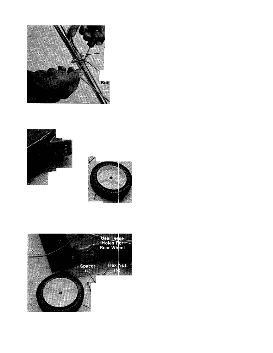
12. Slip the starter rope into the rope guide bolt
------ as shown in figure 12.
FIGURE 12.
J , Use These Holes
For Front Wheel
Hex Nut (N)
Belleville
Washers (M).
Shoulder-'
Bolt (J)
(2V4" Long)
FIGURE 13.
Front Wheel
Bell iviJIe
@/Wash
— Shoulder
Bolt (K)
(2-5/8" Long)
Rear Wheel
FIGURE 14.
INSTALLATION OF WHEELS
If the wheels on your mower are not already
assembled, proceed as follows. The front wheels
must be assembled in one of the three holes
nearest the front of the deck. See figure 13. The
rear wheels must be assembled in one of the three
holes nearest the rear of the deck. See figure 14.
The three holes provide three cutting heights for
your mower. Use the same hole location for aii
four wheels when assembling. To assemble the
-front wheels: (See figure 13)
1. Place shoulder bolt (J) (2V4" long) through
wheel.
2. Place one belleville washer (M) on shoulder
bolt, with the cupped side of washer toward
the deck (away from wheel).
3. Secure wheel to deck with one beileville
washer (M) on the inside of the deck (cupped
side against the deck) and hex nut (N).
if your unit is equipped with handle mount
brackets, assemble the rear wheels in the same
manner as front wheels were assembled.
If the handle on your unit is mounted to the deck
with shouider boits, foliow these instructions
-when assembling the rear wheels. See figure 14.
1. Piace shoulder bolt (K) (2-5/8" long) through
rear wheel.
2. Place spacer (L) on shoulder bolt, next to
wheel.
3. Place one belleville washer (M) on shoulder
bolt, with the cupped side of washer toward
the deck (away from spacer).
4.
Secure wheel to deck with one belleviile
washer (M) on the inside of the deck (cupped
side against the deck) and hex nut (N).