Note, Upper handle installation – MTD 113-080A User Manual
Page 5
Attention! The text in this document has been recognized automatically. To view the original document, you can use the "Original mode".
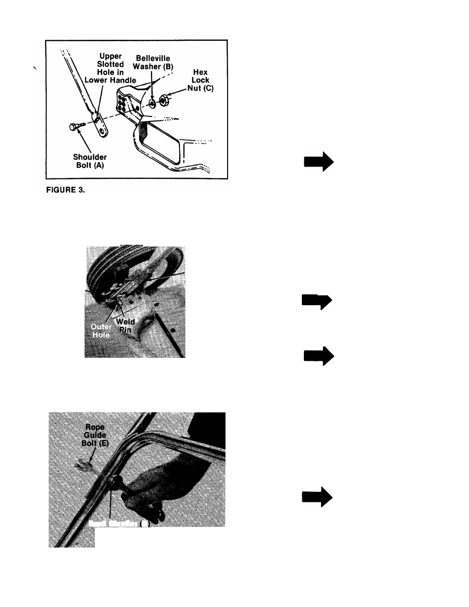
A. Line up the upper slotted hole in lower handle
with the mounting hole on deck. Place
shoulder bolt (A) through lower handle and
deck. See figure 3. Place belleville washer (B)
on the shoulder bolt, with the cupped side of
the washer against the deck. Secure with hex
lock nut (C).
NOTE
It may be necessary to bend the
ends of the lower handle inward
slightly to obtain a tight fit against
the deck.
Hairpin
Cotter (D)
in Inner
Hoie
FIGURE 4.
Lower Handle.
•
" '
«...
Handle
Bracket
B. Place lower handle in position over weld pins
in handle mount brackets on deck, using the
bottom hole in the lower handle. Secure with
hairpin cotters (D) in inner hole on weld pin.
•See figure 4.
NOTE
There are two (2) holes in the handle
mount brackets. Place hairpin cotter
in the inner hole for operation. Outer
hole is for storage.
NOTE
It may be necessary to pull open the
ends of the lower handle to obtain
a tight fit when assembled into
handle mount brackets.
Lock Washer (G)
Hex Nut (H)
UPPER HANDLE INSTALLATION
1.-----Place the upper handle in position over the
lower handle. The throttle control must be on
the right hand side of the handle. Secure the
right hand side of upper handle using the rope
guide bolt (E), lock washer (G) and hex nut (H)
----- as shown in figure 5.
FIGURE 5.
NOTE
Left handed operators may assemble
the rope guide bolt to the left hand
side of the handle for easier starting.
2. Secure the other side of the handle with
curved head bolt (F), lock washer (G) and hex
nut (H).