Note, Lower handle installation, Assembly instructions – MTD 113-080A User Manual
Page 4
Attention! The text in this document has been recognized automatically. To view the original document, you can use the "Original mode".
NOTE
This unit is'shipped WITHOUT GAS
OLINE or OIL. After assembly, see
separate engine manual for proper
fuel and engine oil recommenda
tions.
^3 ^3
ffl-—
FIGURE 1.
ASSEMBLY INSTRUCTIONS
The instructions in this manual cover various
models of mowers. Follow only those Instructions
which pertain to your unit.
NOTE
Reference to right or left hand side
of the mower is observed from the
operating position.
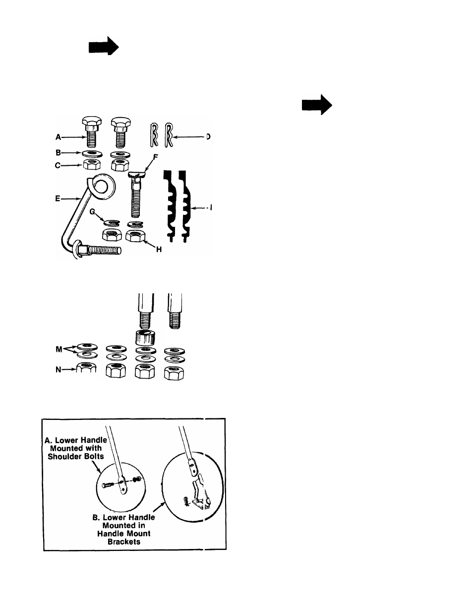
- CONTENTS OF HARDWARE PACK: (See figure 1)
Hardware for Lower Handle Installation
A (2) Shoulder Bolts (070 and 080)
В (2) Belleville Washers 5/16" I.D. (070 and 080)
C (2) Hex Lock Nuts 5/16-18 Thread (070 and
080)
D (2) Hairpin Cotters (072 and 082)
Hardware for Upper Handle Installation
E (1) Rope Guide Bolt
F (1) Curved Carriage Bolt
G (2) Lock Washers 5/16" I.D.
H (2) Hex Nuts 5/16-18 Thread
I (2) Cable Ties
Hardware for Installation of Wheels (if unassem
bled)
J (2) Shoulder Bolts 2У
а
" Long
К (2) Shoulder Bolts 2-5/8" Long
L (2) Spacers
M (8) Belleville Washers 3/8" I.D.
N (4) Hex Nuts 3/8-16 Thread
1. Remove lawn mower and loose parts from car
ton. Make certain all parts and literature have
been removed from the carton before the car
ton is discarded.
2. Extend the throttle control cable (attached to
the upper handle) and the brake cable
(attached to the engine) and place on the
floor. Be careful not to bend or kink control
cables.
LOWER HANDLE INSTALLATION
The lower handle is mounted to the deck by one of
■ two methods. See figure 2.
A.
Models
070
and
080—Shoulder
bolts,
belleville washers and hex lock nuts secure
the handle directly to the deck.
B. Models 072 and 082—Handle is secured to
handle mount brackets on top of the deck
with hairpin cotters.
FIGURE 2.