Attaching the rear wheels (hardware e), Installation of hub caps (optional), Final assembly of mower – MTD 110-518R000 User Manual
Page 8: Assembly of grass catcher (hardware f)
Attention! The text in this document has been recognized automatically. To view the original document, you can use the "Original mode".
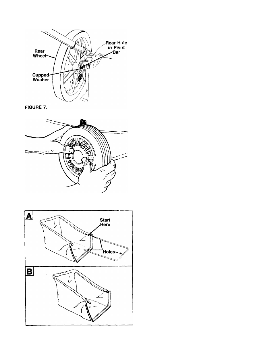
ATTACHING THE REAR WHEELS (Hardware E)
-Assemble the rear wheels as follows. See figure 7.
1. Move the wheel height adjusters so the deck is in
the lowest cutting position.
2. Lift the rear of the unit up and block securely.
3. Insert axle bolt through one rear wheel. Place
cupped washer on axle bolt (crowned side of
washer goes against the wheel).
4. Thread axle bolt into rear hole of pivot bar. Tighten
securely.
5. Assemble other rear wheel in the same manner.
FIGURE 8.—Optional Hub Caps
INSTALLATION OF HUB CAPS (Optional)
1. If your mower is equipped with front hub caps
which have four tabs, line up the tabs on the hub
caps with the holes in the wheels. Push to lock in
position.
2. If your mower is equipped with 2" wide tires, place
front hub caps in position against the inner hub of
the wheel. Press firmly around the center portion
of hub cap in a circular motion, similar to install
ing a lid on a round, plastic container. See figure
------- 8. The hub caps are flexible and will snap over the
3
V
2
" diameter wheel hubs.
FINAL ASSEMBLY OF MOWER
Make certain
all nuts and bolts are tightened securely.
ASSEMBLY OF GRASS CATCHER (Hardware F)
NOTE; Make certain the grass bag is turned right side
out before assembling (warning label will be on the
outside).
1
.
There are three holes in the rear frame. With the
holes on the upper side as shown in figure 9A, in
sert one end of the rear frame into the cloth chan
nel on the edge of the grass catcher bag. Feed all
the material on one side of the frame, then work
■it around the frame. See figure 9B.
FIGURE 9.