Ahaching the throhle control (hardware c), Attaching the brake cable, Securing the cables (hardware d) – MTD 110-518R000 User Manual
Page 7: Attaching the starter rope
Attention! The text in this document has been recognized automatically. To view the original document, you can use the "Original mode".
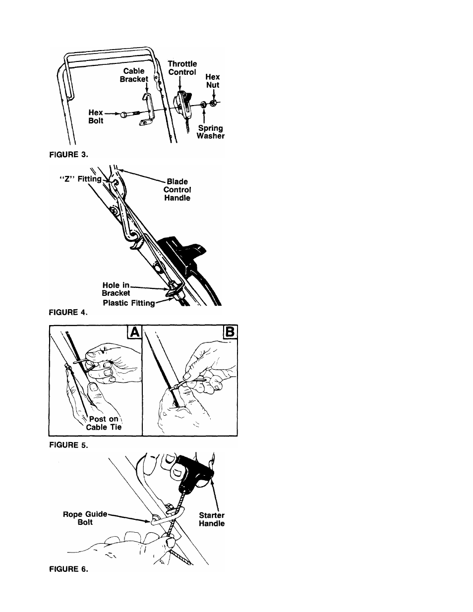
AHACHING THE THROHLE CONTROL (Hardware C)
The throttle control is attached to the engine. Attach
the throttle control to the
left side of upper handle as
-follows. See figure 3.
1. Route the throttle control cable inside the handle
mounting bracket and beneath the lower handle.
2. Place cable bracket against left side of upper han
dle, lining up the hole in the bracket with the bot
tom hole in upper handle. Place 1/4" hex bolt
through cable bracket and handle, from the inside
to the outside.
3. Place throttle control on the hex bolt (outside of
the upper handle), with the throttle lever facing up
ward. Secure with spring washer (cupped side
against the throttle control) and hex nut.
ATTACHING THE BRAKE CABLE
1. The brake cable is attached to the engine, and has
a “Z” fitting on the loose end. Route the brake
cable below the lower handle. Place end of cable
through the hole in the bracket as shown in figure
------- 4. Be careful not to bend or kink the cable at any
time. Push the plastic fitting until it locks into the
hole in the bracket.
A
WARNING: Brake cable must be assem
bled as shown for proper blade brake
operation.
2. Hook the “Z” end of the brake cable into the hole
in the blade control handle from the inside to the
outside as shown in figure 4.
SECURING THE CABLES (Hardware D)
Secure both cables to the left side of the handle as
follows.
1. Insert posts on cable ties into holes provided on
the lower handle. The holes may be either on the
------- inside or outside of the handles. See figure 5A.
2. Secure the cables with the cable ties. See figure
5B.
3. Trim excess ends of cable ties.
ATTACHING THE STARTER ROPE
1. The starter rope is inside the top of the engine. Ad
ditional rope may be wound around the starter han
dle. If so, unwind the rope from the handle.
With the spark plug wire disconnected and
grounded, depress the blade control handle and
pull the rope out of the engine.
Slip the starter rope into the rope guide bolt as
—shown in figure 6.
4.
Tighten the hex nut on the rope guide bolt
securely.
2
.
3.