Assembly instructions – MTD 24604B User Manual
Page 4
Attention! The text in this document has been recognized automatically. To view the original document, you can use the "Original mode".
NOTE
This unit is shipped WITHOUT GAS
OLINE or OIL. After assembly, see
operating section of this manual for
proper fuel and engine oil recom-
A
mendations.
ASSEMBLY INSTRUCTIONS
I' .7
HOLE AND SLOT
IN FRAME
FIGURE 2
_ ^SHOULDER
LOCK WASHER (G) BOLT (F)
A
(1)
B
C
(1)
(1)
i
i
j
t ’ t
i.l iO
D
(1)
r
E
(1)
.4
F
(1)
NOTE
Any reference to right and left hand
will be determined from behind the
edger, in the operator's position.
TOOLS REQUIRED:
Adjustable Wrench.
7/16" Open End or Box Wrench.
9/16" Open End or Box Wrench.
Pair of Pliers.
Hammer
Block of Wood.
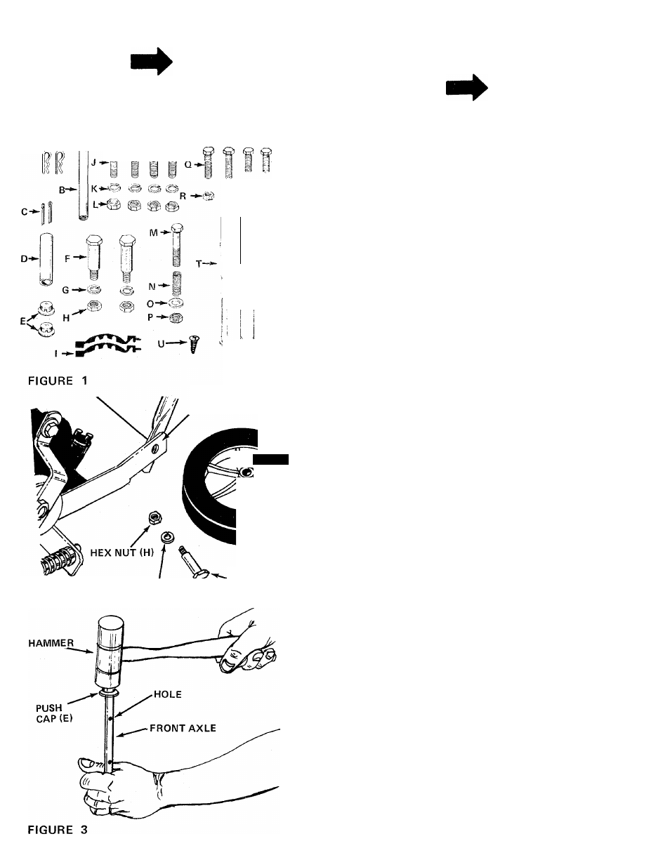
CONTENTS OF HARDWARE PACK:
(See Figure 1)
A (2)
B (1)
C (2)
D (1)
E (2)
F (2)
G (2)
H (2)
I (2)
J (4)
K (4)
L (4)
M (1)
N (1)
0
(
1
)
P (1)
Q (2)
R (4)
S (2)
T (3)
U (1)
Long
X
1.62" Long
Long
Hair Pin Cotters
Rod Adjustment Link
Cotter Pins 1/8" Dia. x 1.00"
Spacer .50" I.D. x .62" O.D.
Push Caps
Shoulder Bolts (Rear Axles)
Lock Washers 3/8" I.D.
Hex Nuts 3/8-16 Thread
Cable Ties
Carriage Bolts 1/4-20 x 1.25"
Lock Washers 1/4" I.D.
Hex Nuts 1/4-20 Thread
Hex Bolt 5/16-18
X
1.75" Long
Compression Spring
Flat Washer
Hex Center Lock Nut 5/16-18 Thread
Hex Bolts 1/4-20 x 1.25" Long
Hex Center Lock Nuts 1/4-20 Thread
Hex Bolts 1/4-20 X 1.00" Long
Grips
Self-Tapping Screw
1. Remove the edger and all parts from the carton.
Make certain that all loose parts and literature
are removed from carton before carton is dis
carded.
2.
Line up holes in lower handle with holes in
frame. Secure rear wheels (larger) and lower
handle to frame with shoulder bolts (F), lock
washers (G) and hex nuts (H). See figure 2.
Using a hammer, tap one push cap (E) onto the
end of the front axle which has a hole closer to it.
See figure 3.