Curved, Carriage bolt (b), Lower – MTD 111-328-300 User Manual
Page 5
Attention! The text in this document has been recognized automatically. To view the original document, you can use the "Original mode".
NOTE
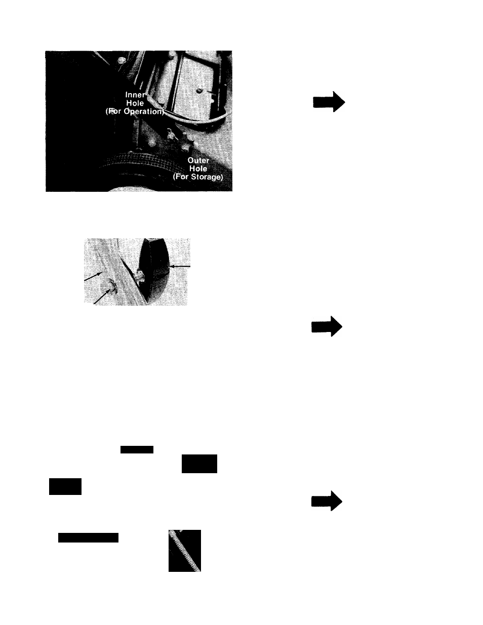
There are two (2) holes in the handle
■ mount brackets. Place hairpin cotter
in the inner hole for operation. The
outer hole is for storage. See figure
3.
FIGURE 3.
Upper
Handle
Curved
Carriage
Bolt (B)
Hand
Knob (A)
r
Lower
Handle
4. Place upper handle over lower handle. Secure
with two carriage bolts (B) and hand knobs (A)
— as shown in figure 4. The knobs can be either
to the inside or the outside of the handle.
NOTE
There are two height positions for
the handle. See adjustment section.
FIGURE 4.
Upper
Handle
Hex Screw (D)
Throttle
, Control
5. Place the throttle control in position on the
right hand side of upper handle. Secure with
hex screw (D) and hex lock nut (E) provided.
— See figure 5.
NOTE
Reference to left or right side of
machine is from operator’s position
at the handle facing forward.
FIGURES.