Assembly, Instructions, Note – MTD 111-328-300 User Manual
Page 4: Le t, Assembly instructions
Attention! The text in this document has been recognized automatically. To view the original document, you can use the "Original mode".
Assembly
of
Mower
A^
■le T
B —
F—►
G
H
Assembly
of
Grass
Catcher
FIGURE 1.
ASSEMBLY
INSTRUCTIONS
NOTE
This unit is shipped WiTHOUT GAS
OLINE or OIL. After assembly, see
operating section of this manuai for
proper fuel and engine oil recom
mendations.
Contents of Hardware Pack
A (2)
B (2)
-C (2)
D (1)
E (1)
F (2)
Hand Knobs
Curved Carriage Bolts 5/16-18 x 1.75" Long
Cable Ties
Hex Screw V4-20 x 1.50" Long
Hex Center Lock Nut V4-20Thd.
Hairpin Cotters
G (7) Truss Head Bolts 3/8" Long
H (7) External Lock Washers
I (7) Hex Nuts #10-24 Thread
■J (2) CotterPins
1. Remove the lawn mower, loose parts, hard
ware pack and literature from the carton.
Make certain all parts and literature have been
removed before the carton is discarded.
2. Extend the throttle control which is attached
to the mower and place on the floor. Be
careful not to bend or kink control wire.
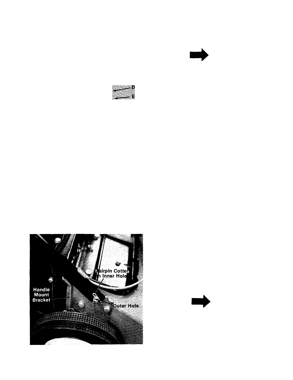
3. Place lower handle in position over weld pins
in handle mount brackets on deck. Secure by
placing two hairpin cotters (F) in inner hole on
— weld pins. See figure 2.
NOTE
It may be necessary to bend the
ends of the lower handle inward
slightly to assure a snug fit against
the bracket mounting area.
FIGURE 2.