MTD 215-395A User Manual
Page 5
Attention! The text in this document has been recognized automatically. To view the original document, you can use the "Original mode".
CONTROL ASSEMBLY (See figure 7.)
Throttle Control Assembly
Assemble control lever in box on handle panel as
shown. Be sure control lever is positioned with the
hole in the control rod mounting clevis up (or to
the rear).
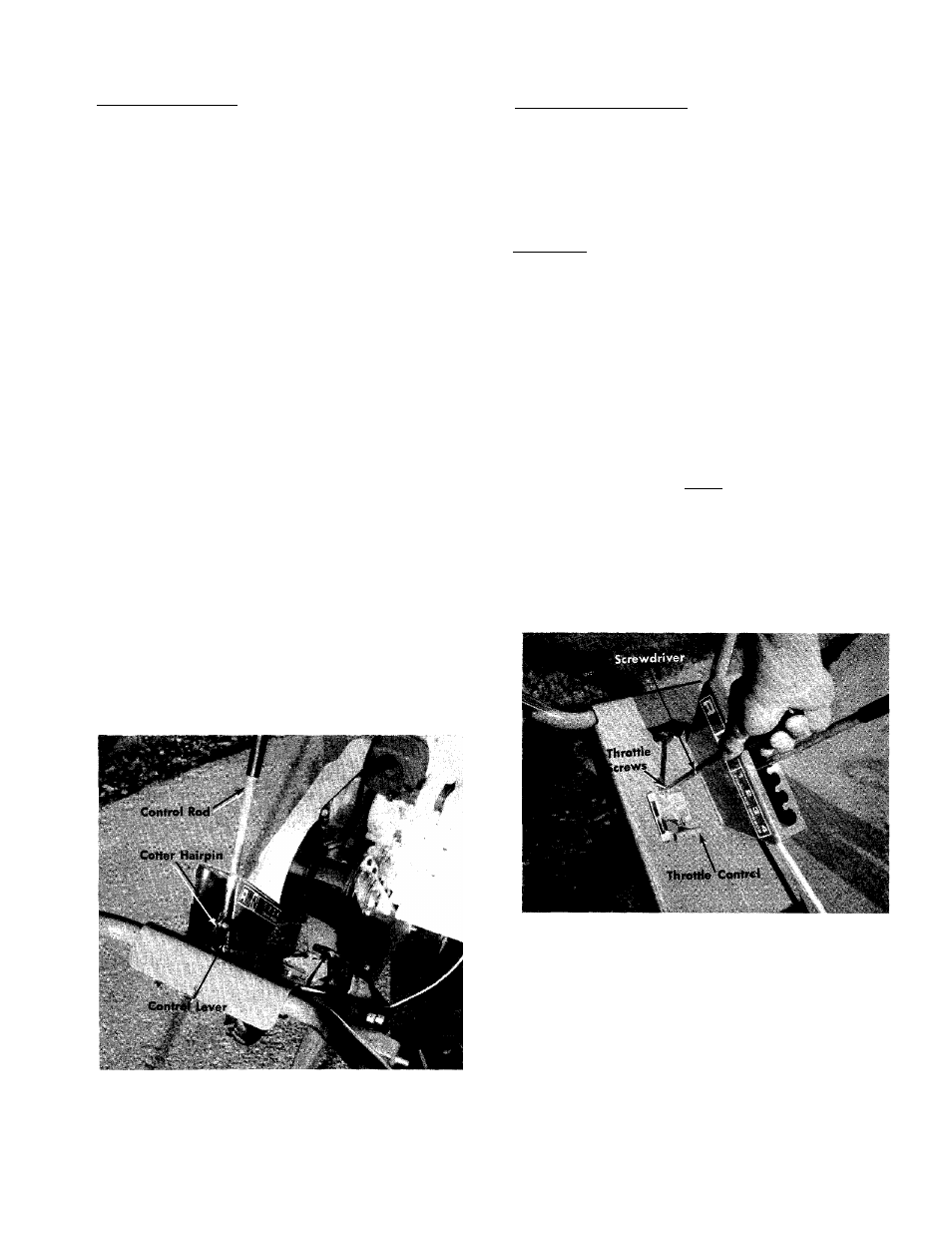
Step 1. Place throttle control in handle and assemble
to handle with the two throttle screws using
a screwdriver. See figure 8.
2. Insert the "L" shaped end of control rod through
the lower opening of the box. Screw the threaded
end of the control rod into the ferrule on the vari
able speed control. It will extend approximately
3. Insert the "L" shaped end of the control rod into
the control lever and fasten with cotter pin.
4. Remove spark plug wire. Place control lever in neu
tral. Pull recoil starter rope several times. Tines
should not rotate. If tines rotate, adjust control rod
in ferrule until "NEUTRAL" is obtained.
5. Replace spark plug wire.
CAUTION
If the belt cover (Ref. No. 63 on page
12) is removed, you will not have any
neutral. This belt guard contains the
belt trapout meant for around the en
gine pulley. The control rod must be as
sembled exactly as noted above and as
shown in figure 7 or there will be no
neutral and the tiller tines will rotate
as long as the engine runs.
CONTROLS
The controls on your Rotary Tiller are the control lever,
throttle control and depth bar.
The Control Lever
The Control Lever is released from Neutral by moving
it to the right and allowing the spring tension to pull
the control lever into one of the four forward speeds.
See figure 9.
NOTE
Number 1 position is the slowest tine
rotation speed and number 4 is the
fastest.
Pulling the control lever slowly backwards into Re
verse position reverses the direction of tine rotation.
Reversing should be done at half throttle position.
FIGURE 9. CONTROLS
FIGURE 8. THROmE CONTROL