Belt replacement, Caution, Note – MTD 215-395A User Manual
Page 10: Carburetor adjustment see figure 22
Attention! The text in this document has been recognized automatically. To view the original document, you can use the "Original mode".
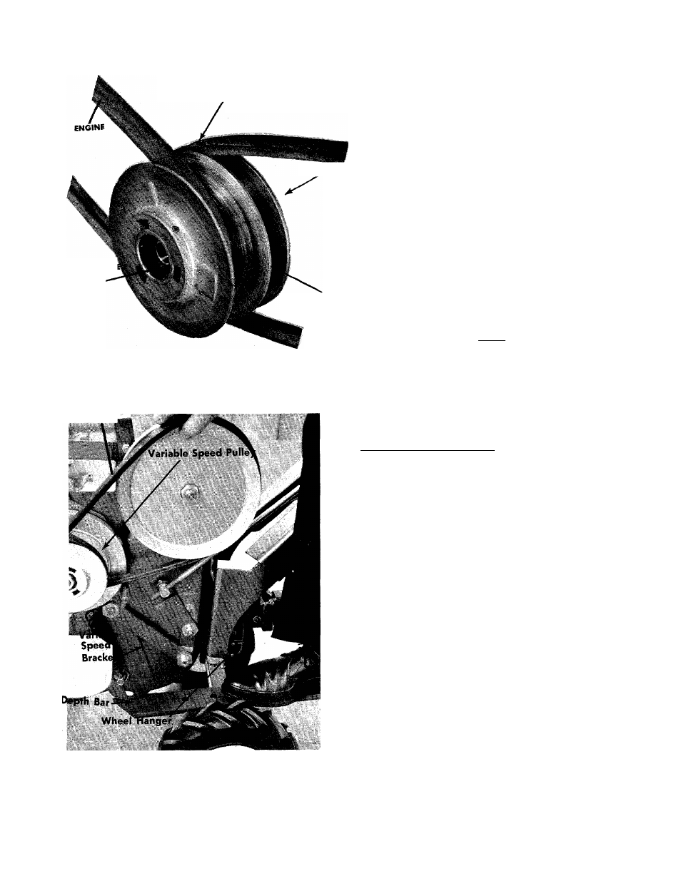
BEIT SHOUIO BE IN THIS
POSITION WITH CONTROL
LEVER IN NO. 4 POSITION
BELT REPLACEMENT
CAUTION
Be careful not to pinch your fingers be-
tv/een the pulley and belt.
Step 1. Remove the belt cover so the belts are ex
posed as shown in figure 19.
CHAIN CAS’E
Step 2. Put the depth bar on the wheel hanger and
place the tip of the depth bar under the var
iable speed pulley bracket as shown in figure
21.
VARIABLE SPE
PULLEY
Step 3. Place your foot on the rear of the depth bar
and apply pressure. The belts will go slack.
Step 4. Remove the REAR belt first and allow it to
form a loop around the variable speed pulley.
Step 5. Slide the center section of the variable speed
pulley towards the engine. See figure 19.
CENTER SECTION
Step
6.
Remove the FORWARD belt from the engine
pulley and the variable speed pulley.
FIGURE 20. VARIABLE SPEED PULLEY
Rear Beh
NOTE
By following this order of bfelt removal,
it is not necessary to remove the belt
guard on the variable speed pulley.
Step 7. Remove the rear belt from the variable speed
pulley.
Step 8. Reassemble with the new belts.
CARBURETOR ADJUSTMENT See figure 22.
Minor carburetor adjustment may be required to com
pensate for differences in fuel, temperature, altitude
and load. To adjust:
Step 1. Turn needle valve clockwise until it just closes.
CAUTION
FIGURE 21. BELT REMOVAL
Valve may be damaged by turning too
far.
Step 2. Open needle valve 114 turns counterclockwise.
Step 3. Close the idle valve in the same manner and
open 114 turns.
4. Start the engine.
5. Turn the needle valve in until the engine
misses,
6. Then turn it out past smooth operating point
until the engine runs unevenly.
Step 7. Turn the needle valve mid-point between the
two settings so the engine runs smoothly.
Step 8. Set the throttle in the idle (slow) position and
set the idle speed adjusting screw until a fast
idle is obtained.
St^ 9. With the throttle stilLin the idle position, turn
the idle valve in and out until the engine idles
smoothly.
Step
Step
Step
10