MTD 197-987A User Manual
Page 3
Attention! The text in this document has been recognized automatically. To view the original document, you can use the "Original mode".
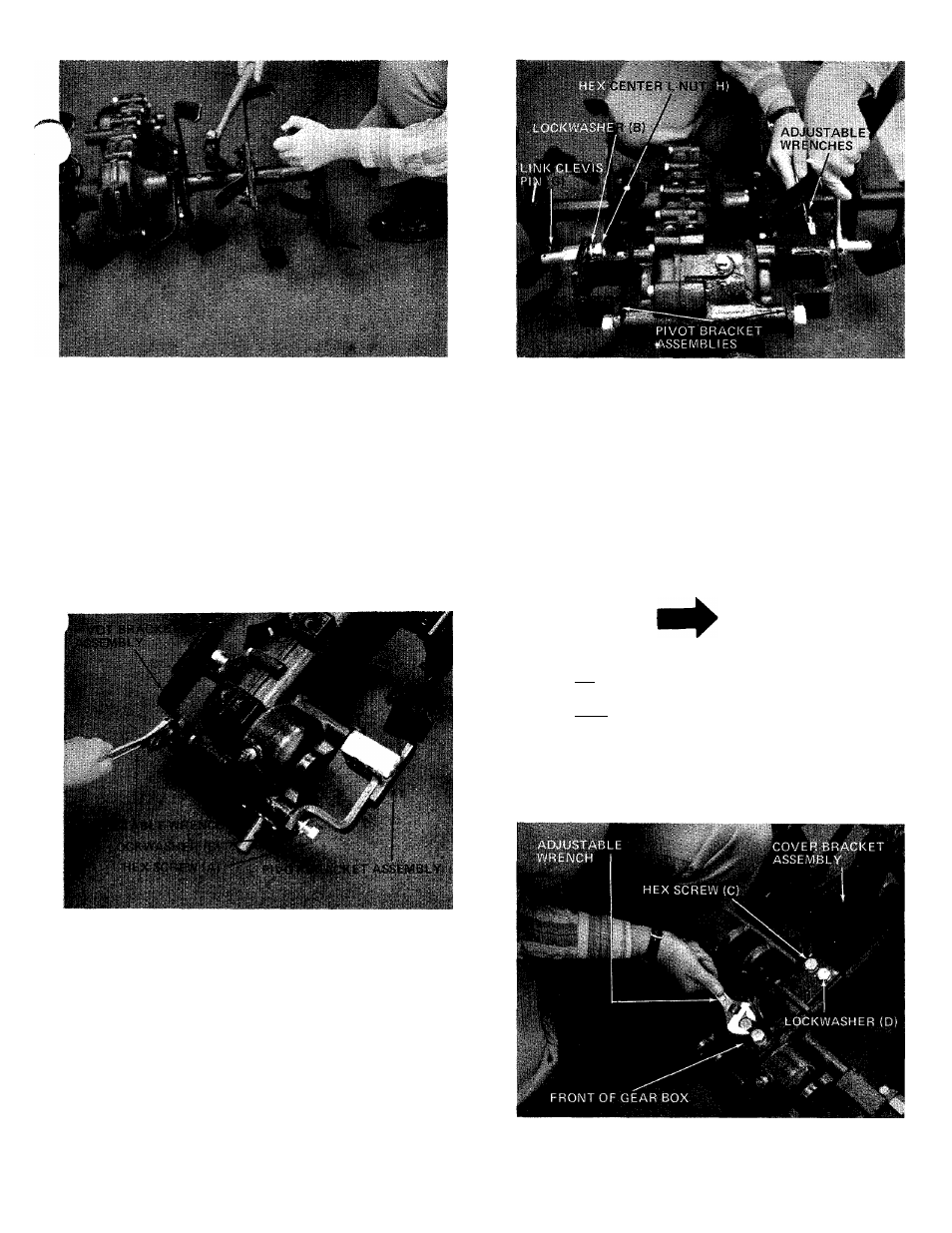
FIGURE 4
FIGURE 6
5. Install tiller pivot bracket assemblies. An adjust
able wrench is required. Place pivot bracket in
position on gear box as shown in figure 5. Secure
with four hex screws (A) and lockwashers (B).
See figure 5.
Install cover bracket assembly to gear box (as
shown in figure 7) using four hex screws 1/2-13 x
1-1/4" (C) and 1/2" lockwashers (D). An adjust
able wrench is required.
FIGURES
j.
Insert link clevis pins (G) through outside holes
of pivot bracket assemblies. Using two adjustable
wrenches, tighten link clevis pins in place with
lockwashers 5/8" (B) and hex center lock nuts
5/8-18 (H). See figure 6.
NOTE
All hex screws should be hand tight
ened. When _aiL screws are in place,
then tighten with adjustable wrench.
FIGURE 7