Assembly instructions – MTD 197-987A User Manual
Page 2
Attention! The text in this document has been recognized automatically. To view the original document, you can use the "Original mode".
Your new tiller attachment comes unassembled from
the factory. You will need two adjustable wrenches
and one hammer to complete the assembly of your
tiller.
LIST OF CONTENTS IN HARDWARE PACK.
(See figure 1)
A (4) Hex Screws 5/8-11 x 1-1/2" long
B (6) Lockwashers for 5/8" screw
C (4) Hex Screws 1/2-13 x 1-1/4" long
D (4) Lockwashers for 1/2" screw
E (4) Spring pins 3/8" Dia. x 2" long
F (3) Hair pin cotters for 5/8" Dia.
G (2) Link Clevis Pins
H (2) Hex Lock Nuts 5/8-18 Thread
I (1) Clevis Pin 5/8" Dia. x 2" long
J (4) Hex Screws 5/16-24 x 3/4" long
K (4) Lockwashers for 5/16" screw
L (4) Hex Nuts 5/16-24 Thread
M (2) Hair Pin Cotters for 3/8" Dia.
N (2) Clevis Pins 3/8" Dia. x 1-1/4" long
O (1) Spring Pin 5/16" Dia. x 1-3/4" long
P (1) Square Head Pipe Plug-Vented
Q (10) Carriage Bolts 5/16-18 x 1" long
R (10) Lockwashers for 5/16" Screw
S (10) Hex Nuts 5/16-18 Thread
REPLACE WITH
VENTED PIPE PLUG (P)
_ADJUStABLE
WRENCH
FIGURE 2
3. With an adjustable wrench remove the pipe plug
and replace with vented pipe plug (P) provided in
hardware parts pack. See figure 2.
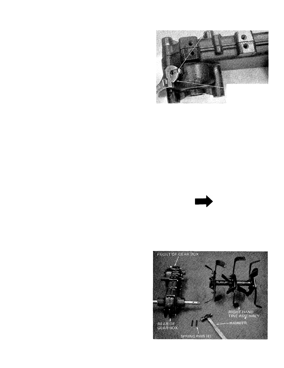
4. Assemble the right and left hand tine assemblies
to gear box, with four spring pins (E). A hammer
is required. See note below before continuing.
■I
'
I
■
IB
NOTE
Right and left hand is determined
from behind the gear box. The sharp
edge of the tines must enter the soil
first. See figures 3 and 4.
FIGURE 1
ASSEMBLY INSTRUCTIONS
1. Remove the tiller, all loose parts and hardware
parts pack from the carton before discarding the
carton.
2. Place the gear box so that the pipe plug is up, as
shown in figure 2.
FIGURES