To assemble the front wheels, To assemble the rear wheels, Note – MTD 113-050A User Manual
Page 5
Attention! The text in this document has been recognized automatically. To view the original document, you can use the "Original mode".
Hex
Nut (E)
Belleville ^
Washers (D)'Sk,
Shoulder
Bolt (A)
(2V4" Long)
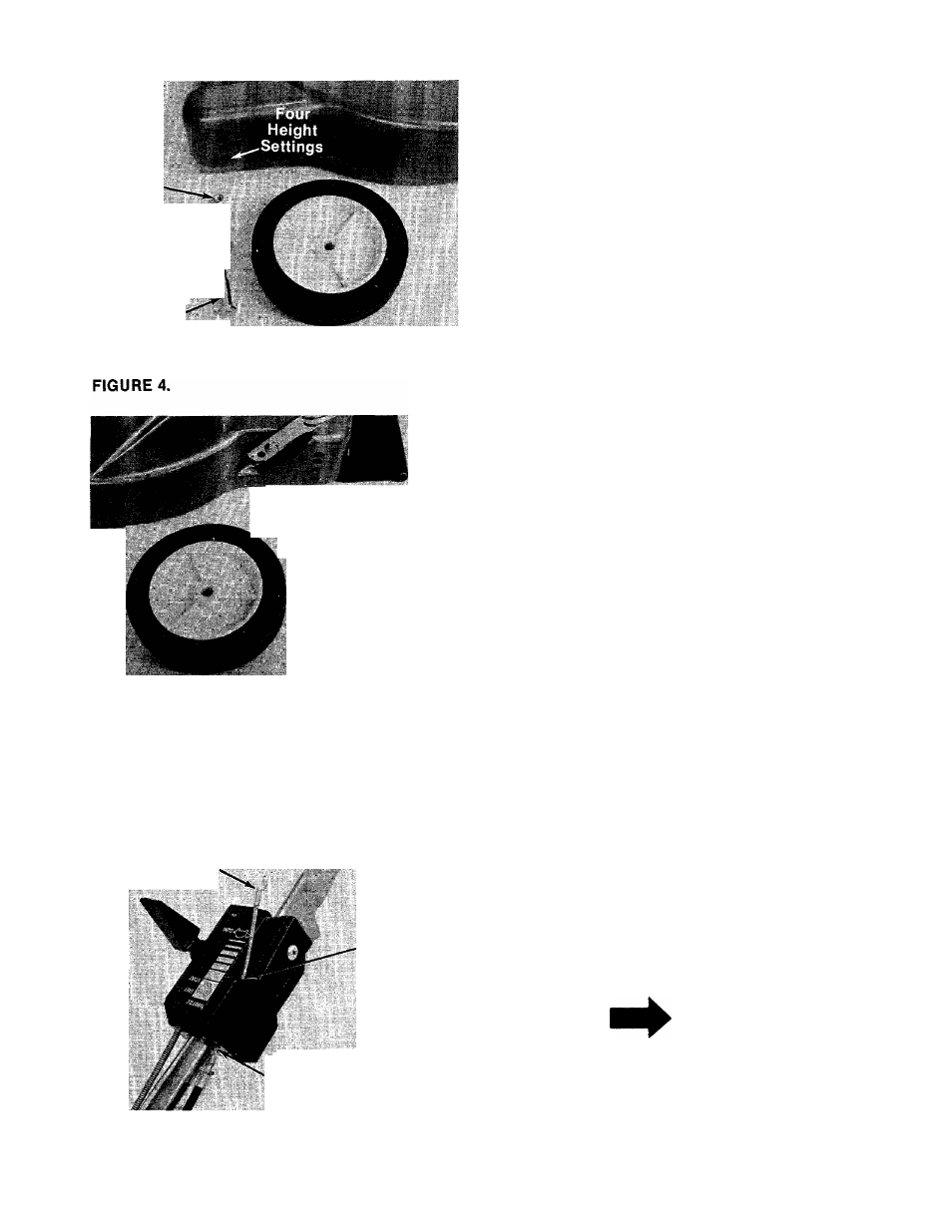
6. Your mower has four height settings. Use the
same mounting hoie for all four wheels when
— assembling. See figure 4.
To Assemble the Front Wheels:
A. Place shoulder bolt (A) (2V4" Long) through
wheel.
B. Place cupped side of belleville washer (B)
towards the deck (away from wheel).
C.
Place shoulder bolt through desired
mounting hole on deck. Secure with
belleville washer (D) (cupped side goes
against the deck) and hex nut (E).
Four
i
Height
Settings
^Hex
,-*""^ut (E)
B.
Belleville
y Washers (D)
c.
^Spacer (C)
D.
i
Shoulder
i'-Bolt (B)
|f2-5/8" Long)
To Assemble the Rear Wheels:
A.
Place shoulder bolt (B) (2-5/8" Long)
—through rear wheel. See figure 5.
Place spacer (C) on shoulder bolt, next to
wheel.
Place one belleville washer (D) on shoulder
bolt, with the cupped side of washer
toward the deck (away from the spacer).
Secure wheel to deck with one belleville
washer (D) on the inside of the deck
(cupped side against the deck) and hex nut
(E).
FIGURE 5.
Brake
Cable
Slot
Upper Hole
on Bottom of
Housing
7. Place the end of the brake cable into the up
per hole on the bottom of the throttle control
housing, and through the slot as shown in
—figure 6. Be careful not to bend or kink the
cable.
NOTE
The control cables should be as
sembled under the lower handle.
FIGURE 6.