Note, Assembly instructions, Contents of hardware pack: (see figure 1) – MTD 113-050A User Manual
Page 4
Attention! The text in this document has been recognized automatically. To view the original document, you can use the "Original mode".
NOTE
This unit is shipped WiTHOUT GAS-
OLiNE or OiL After assembiy, see
separate engine manuai for proper
fuei and engine oii recommenda
tions.
FIGURE 1.
V\
Upper
Slotted
Deck
Hex
Look
Nut (I)
Belleville
Washer (H)
Shoulder Bolt
(G)
FIGURE 2.
Rope
Guide
Boit (J)
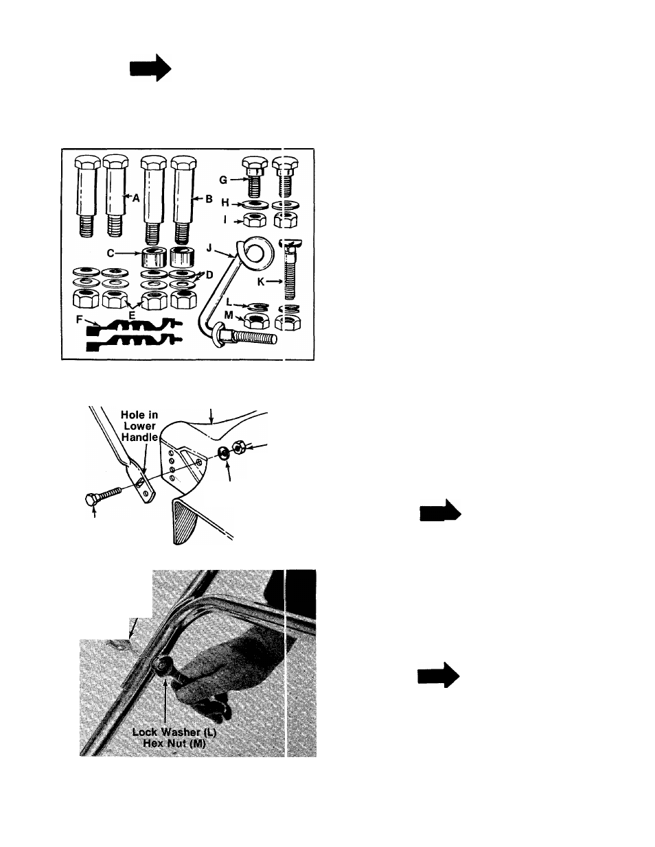
ASSEMBLY INSTRUCTIONS
Contents of hardware pack: (See figure 1)
A (2) Shouider Bolts
21
/
4
" Long
B (2) Shoulder Bolts 2-5/8" Long
C (2) Spacers
D (8) Belleville Washers 3/8" I.D.
E (4) Hex Nuts 3/8-16 Thread
F (2) Cable Ties
G (2) Shoulder Bolts 5/16-18 Thread
—H (2) Belleville Washers 5/16" I.D.
I (4) Hex Lock Nuts 5/16-18 Thread
J (1) Rope Guide Bolt
K (1) Curved Head Carriage Bolt
L (2) Lock Washers 5/16" I.D.
M (2) Hex Nut 5/16-18 Thread
1. Remove lawn mower and loose parts from car
ton. Make certain all parts and literature have
been removed from the carton before the car
ton is discarded.
2. Extend the throttle control cable (attached to
the upper handle) and the brake cable
(attached to the engine) and place on the
floor. Be careful not to bend or kink control
cables.
3. Line up the upper slotted hole in the lower
handle with the mounting hole on deck. Place
shoulder bolt (G) through lower handle and
deck. Place belleville washer (H) on the
shoulder bolt, with the cupped side of the
washer against the deck. Secure with hex lock
------- nut (I). See figure 2.
NOTE
It may be necessary to bend the
ends of the lower handle inward
slightly to obtain a tight fit against
the deck.
4. Place the upper handle in position over the
lower handle. The throttle control must be on
the right hand side of the handle. Secure the
right hand side of upper handle using the rope
guide bolt (J), lock washer (L) and hex nut (M)
—as shown in figure 3.
FIGURE 3.
NOTE
Left handed operators may assem
ble the rope guide bolt to the left
hand side of the handle for easier
starting.
5. Secure the other side of the handle with
curved head bolt (K), lock washer (L) and hex
nut (M).