Assembly instructions – MTD 246-632-000 User Manual
Page 5
Attention! The text in this document has been recognized automatically. To view the original document, you can use the "Original mode".
TO#
t
4
^ c —
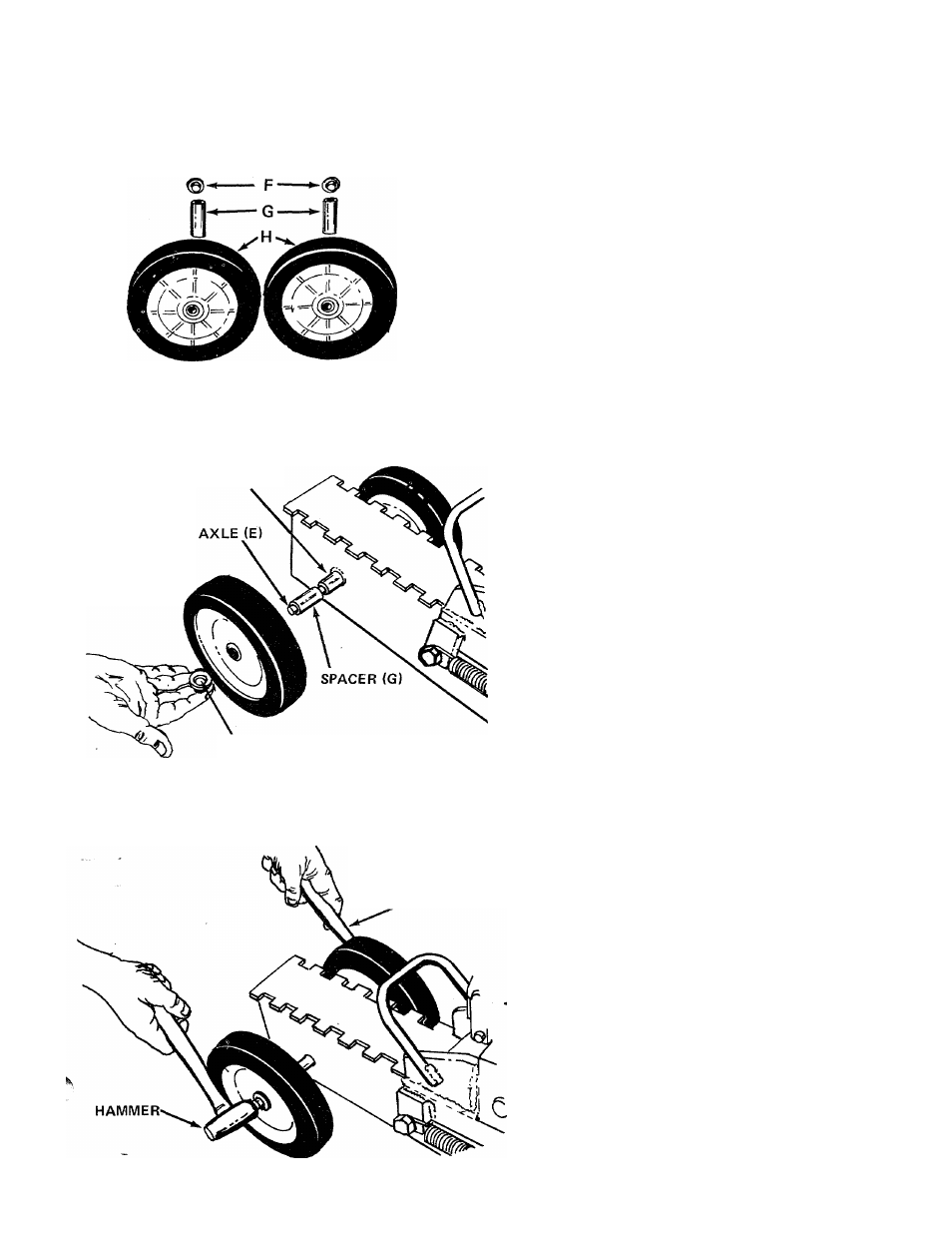
FIGURE 1
WELDED TUBE
WHEEL (H)
\
ASSEMBLY INSTRUCTIONS
CONTENTS
OF
HARDWARE
PACK
AND
LOOSE
- PARTS: (See Figure 1)
PUSH ON CAP (F)
A (1) Handle Grip
B (1) Handle
C (1) Hairpin Cotter (may be rings)
D (1) Clevis Pin (may be pin)
E (1) Axle
F (2) Push on caps 1/2" Dia.
G (2) Spacers
H (2) Wheels
1.
Remove the log splitter, loose parts and literature
from carton. Check to be sure all parts are removed
from carton before discarding the carton.
2.
Place the axle (E) through the welded tube on
' splitter. See figure 2.
3.
Next, place spacers (G) on each side of splitter,
over axle. See figure 2.
figure
2
USE A SECOND
HAMMER, OR BLOCK
OF WOOD
4.
5.
Next, place wheels (H) over each end of axia
See figure 3.
Secure wheels to axle with push on caps (F). A
hammer
and block of wood will be required to
hammer on the caps. See figures 2 and 3.
FIGURE 3