Operating instructions, Generator control panel, Optional remote start/stop panel – Generac 9600-3 User Manual
Page 8: Before starting the engine
Attention! The text in this document has been recognized automatically. To view the original document, you can use the "Original mode".
OPERATING INSTRUCTIONS
GENERATOR CONTROL PANEL
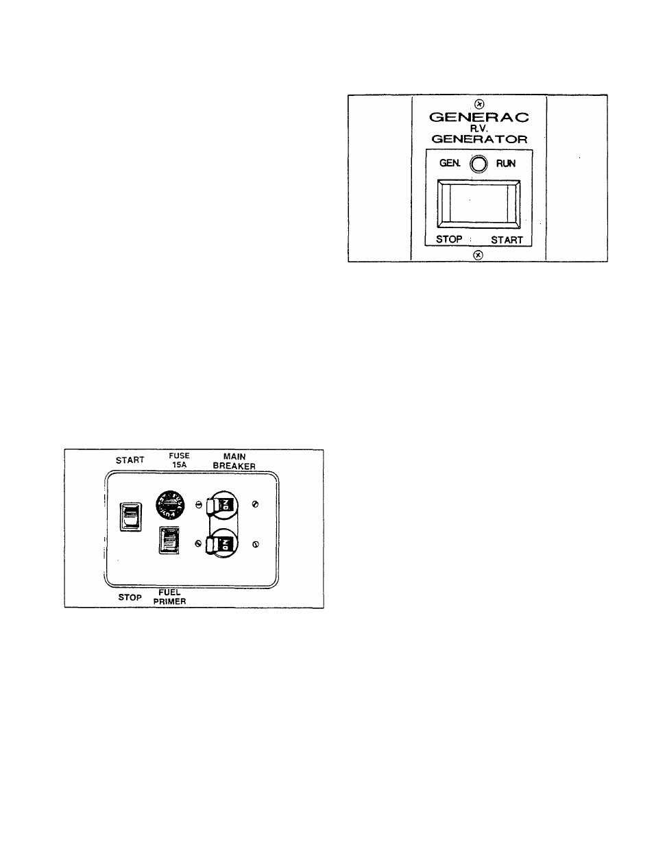
Mounted on the generator control panel (Figure 2) are
the following features:
•
Fuel Pump Primer: Before starting a cold engine
(it has not been started in more than two weeks),
you must press this switch to bring fuel from the tank
to the fuel pump. This rocker t^e switch springs
back into its original position when you release it.
•
StarVStop Switch: To crank and start the engine,
hold this switch at its START position. Release the
switch when the engine starts. To stop an operating
engine, place the switch in its STOP position. The
switch center position is the RUN position.
•
15
amp Fuse: Protects the engine DC control
circuit against electrical overload. If the fuse ele
ment has melted open due to overloading, the en
gine cannot be cranked. If you must replace it, use
only an identical IS.amp replacement njse.
« Line Breakers; Protects generator’s AC output
circuit against overload, i.e., prevents unit from
exceeding
wattage/amperage
capacity.
NP-66G
has one 20-amp and one 30-amp breaker.
NOTE: If the SeriesQ-66G has been reconnected for
dual voltage AC output (120/240 volts), you can install
line breakers having an amperage rating that is different
than stated above. The replacement line breakers con
sist of two separate breakers with a connecting piece
between the breaker handles (so that both breakers will
operate at the same time). If the unit is reconnected for
dual voltage, it is no longer RVIA listed.
Figure 2 — Typical Control Panel
OPTIONAL REMOTE START/STOP PANEL
Optional remote mounted panels are available which
permit you to crank and start the generator from any
convenient location in the recreational vehicle. Figure 3
shows the Model 9042 remote panel which includes (a)
start/stop switch and (b) a generator run lamp.
You can also order Model 9043, a remote panel which
includes the (a) start/stop switch, (b) the generator run
lamp and (c) an hourmeter. The hourmeter provides a
continuous
indication
of
engine-generator
operating
time. Use the hourmeter for checking off periodic main
tenance requirements on the unit.
Figure 1 — Optional Remote Panel (Model 9042)
AUTOMATIC CHOKE
The engine is equipped with an automatic choke that
consists of two main components—choke solenoid and
prechoke.
Choke Solenoid: During engine cranking (start/stop
switch at START), a solid state choke module signals
the choke solenoid to actuate and cycle (choke
on/choke off) until engine starts. The choke solenoid
thus opens and closes the carburetor choke valve only
when the engine is cranking. When the engine starts,
the choke cycling stops.
Prechoke: The choke system also has a temperature
sensitive metal strip that adjusts the choke valve angle
according to ambient temperatures (i.e. in cold ambient
temperatures the choke valve closes more). Once the
engine starts, an element heats the temperature-sensi
tive strip to a normal operating condition, opening the
choke valve. This may take about 3 minutes in cooler
weather.
BEFORE STARTING THE ENGINE
IMPORTANT:
INSTRUCTIONS
AND
INFORMATION
IN THIS MANUAL ASSUME THE GENERATOR HAS
BEEN
PROPERLY
INSTALLED,
CONNECTED,
SERVICED, TESTED AND ADJUSTED BY A QUALI
FIED INSTALLATION TECHNICIAN OR INSTALLA
TION CONTRACTOR.
•
Installation: Generator installation must have
been properly completed so it complies with all
applicable codes, standards and regulations and
with the manufacturer’s recommendations.
•
Engine Lubrication:
Have engine crankcase
properly serviced with recommended oil before
starting. Refer to “Maintenance" and “Specifica
tions" sections for oil servicing procedures and rec
ommendations.
CAUTION: Any attempt to crank or start the engine
before you have properly serviced it with the recom
mended oil will result in an engine failure.
- 6 -