Assembly - one piece handle, Clutch control lever assembly, Assembly - handle with – MTD 219-100 User Manual
Page 4: Small handle panel, Check list before operation
Attention! The text in this document has been recognized automatically. To view the original document, you can use the "Original mode".
ASSEMBLY - ONE PIECE HANDLE
Your rotary tiller is shipped complete in a single carton.
The tines, wheels, handles, controls and depth bar are to be
assembled. This is done in the manner described below.
TINES — Mount tines on tine shaft as shown. Tines must
be mounted with the cutting edges facing the front. The
tiller will not operate properly unless the sharpened sur
face of the tines enter the soil first. Secure tines in posi
tion on tine shaft with cap screws (47), and nuts (46).
NOTE: Dust pads (68 & 69) are provided in screw pack.
WHEELS: Insert axle bolts (31) into wheel hubs. Se
cure with locknuts (32) tightened only enough to allow
free movement of the wheels (26). Attach wheel and axle
assemblies to outside of tiller legs (10 & 11). Fasten with
locknuts (32) as shown.
HANDLE — Assemble the handle brackets (110) to the
handle (107) with hex head screw (115), lockwashers (44)
and hex nuts (114). Do not tighten. Place the handle (110)
in the tail piece slots. Fasten the lower hole in the handle
brackets to the frame with a carriage bolt 5/16—18 x Ig.
(50), lockwasher (51) and hex nut (54). Tighten all screws
and nuts.
CLUTCH CONTROL LEVER ASSEMBLY
Lockout Lever. Place the hex head screw
i^-20
x 1^
(116) through the hole in the tab below the slot in the
handle panel from the right hand side. Assemble in this
order: Rubber washer, lock out rod (rod bracket to the
front), steel washer and lock nut. Tighten until rubber
washer compresses slightly.
Clutch control assembly. Screw the ferrule (105) on
the threaded end of the lock out rod (104) until about
Vz”
of the threads show. Insert the ferrule through the
control lever (15), fasten with flat washer (111) and cotter
hairpin (113). Put the lockout handle in the neutral posi
tion. Insert the lockout rod in the bracket on the lockout
lever and secure with a cotter hairpin through the center of
the bracket. Adjust the ferrule so both belts are slack when
the lockout lever is in the neutral position.
DEPTH BAR — Attach depth bar (12) in desired posi
tion with clevis pin (29) and locking pin (28).
GRIPS — Assemble grips (22) to handle bars.
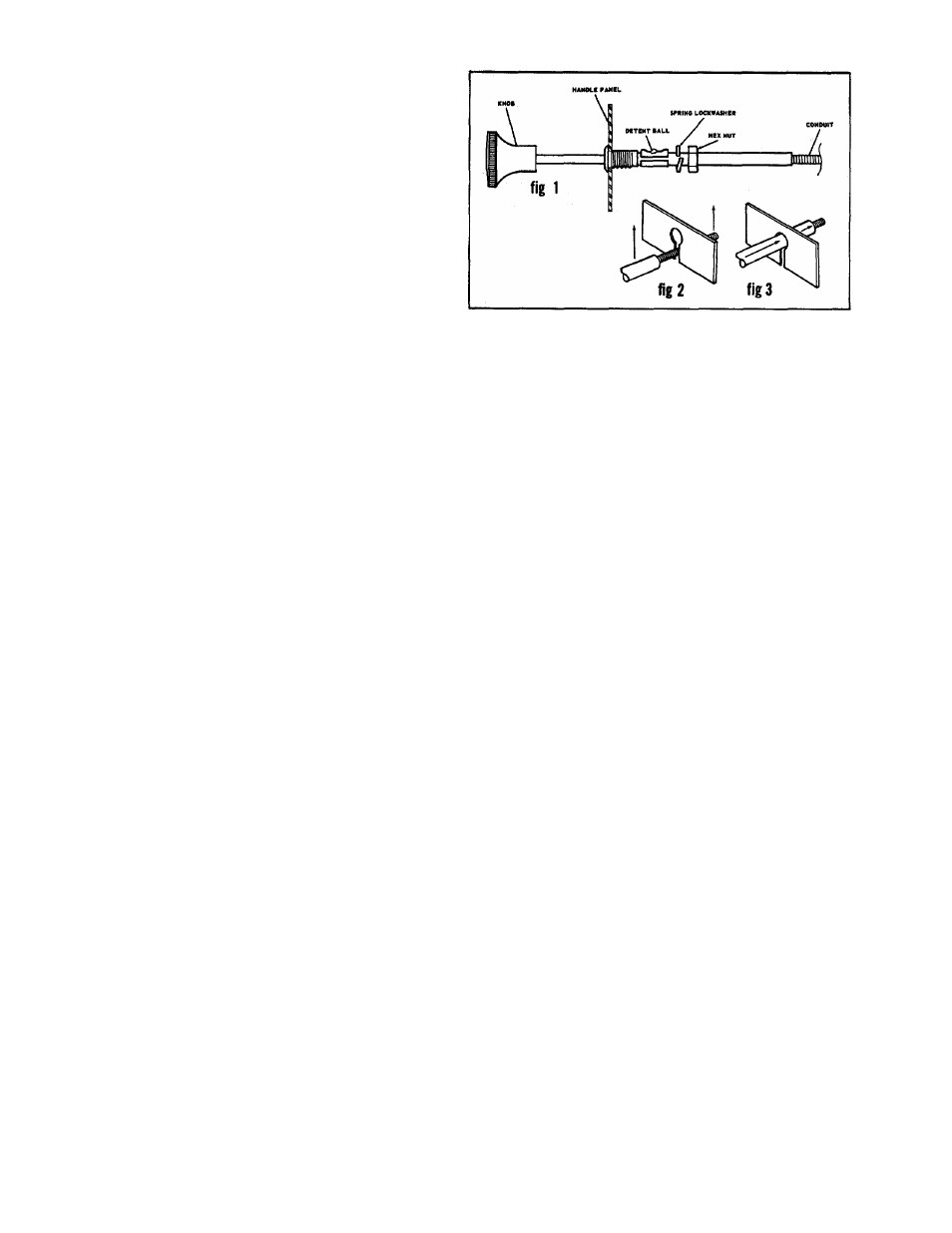
THROTTLE — To assemble the throttle push the black
plastic knob in all the way then pull it out until the detent
ball clicks into the second notch. The knob will be pulled
out approximately 1-3/8” when in the second notch. In
this position the spring lockwasher and hex nut will slide
past the detent ball. Place the conduit through the slot in
the handle panel (see fig 2) and push the unit (see fig 3) in
until it seats as shown see (fig 1). Secure with the spring
lockwasher and hex nut.
TINES — Mount tines on tine shaft as shown. Tines must
be mounted with the cutting edges facing the front. The
tiller will not operate properly unless the sharpened sur
face of the tines enter the soil first. Secure tines in posi
tion on tine shaft with cap screws (47), and nuts (46).
NOTE: Dust pads (68 & 69) are provided in screw pack.
These must be assembled as shown.
WHEELS — Insert axle bolts (31) into wheel hubs. Secure
with locknuts (32) tightened only enough to allow free
movement of the wheels (26). Attach wheel and axle as
semblies to outside of tiller legs (10 & 11). Fasten with
locknuts (32) as shown.
HANDLES — Insert handles (8 & 9) into slots in tailpiece
assembly (3). NOTE: The handles are left (9) and right
(8) and must be positioned accordingly. Secure handles in
position with cap screws (48) through the upper mounting
holes and the tailpiece bracket (24). Fasten with lock-
washers (44) and nuts (45). Do not tighten. Select desired
handle position and secure lower part of handle with car
riage bolts (50), lockwashers (51) and nuts (54). Do not
tighten.
HANDLE PANEL —Position handle panel (13) over upper
handles and attach with carriage bolt (72) and locknuts
(35). The throttle control is mounted on the under side of
the left handle. Fasten with carriage bolt (72) through up
per handle hole and through the middle hole in the con
trol (64) mounting plate. Fasten control cable to handle
with cable clip (67). Tighten all nuts securely.
CLUTCH CONTROL — Insert lower end of control rod
(19) into control lever (15), mounting hole from left side.
Attach adjustment tube (101) to control rod and adjust
for approximate length. Attach tube to control handle
assembly (6) with cap screw (102) and stop nut (103).
Readjust if necessary.
DEPTH BAR — Attach depth bar (12) in desired position
with clevis pin (29) and locking pin (28).
GRIPS — Assemble grips (22) to handle bars.
ASSEMBLY - HANDLE WITH
SMALL HANDLE PANEL
Your rotary tiller is shipped complete in a single carton.
The times, wheels, handles, controls and depth bar are to
be assembled. This is done in the manner described below.
CHECK LIST BEFORE OPERATION
1. Check tiller tines for proper installation. With throttle
control lever set on “Stop” position and the clutch con
trol handle set in “Forward” position, slowly crank en
gine to determine direction of tine rotation. Be sure all
tines are mounted so the sharpened edges enter the soil
first.
FORM NO. 770-1881 D