MTD 216-320-000 User Manual
Page 6
Attention! The text in this document has been recognized automatically. To view the original document, you can use the "Original mode".
Handle
Panel
NOTE
If
the
handle
panel
was
preas
sembled on your unit, omit steps 4
and 5.
Place the handle panel in position on the handles.
Secure with four carriage bolts (A), lock washers
(B) and hex nuts (C). See figure 7.
5. Tighten securely hex nuts (C) with
Vz"
wrench.
6. Tighten securely hex bolts on lower handle (figure
6) with two 9/16" wrenches.
FIGURE 7.
FIGURE 8.
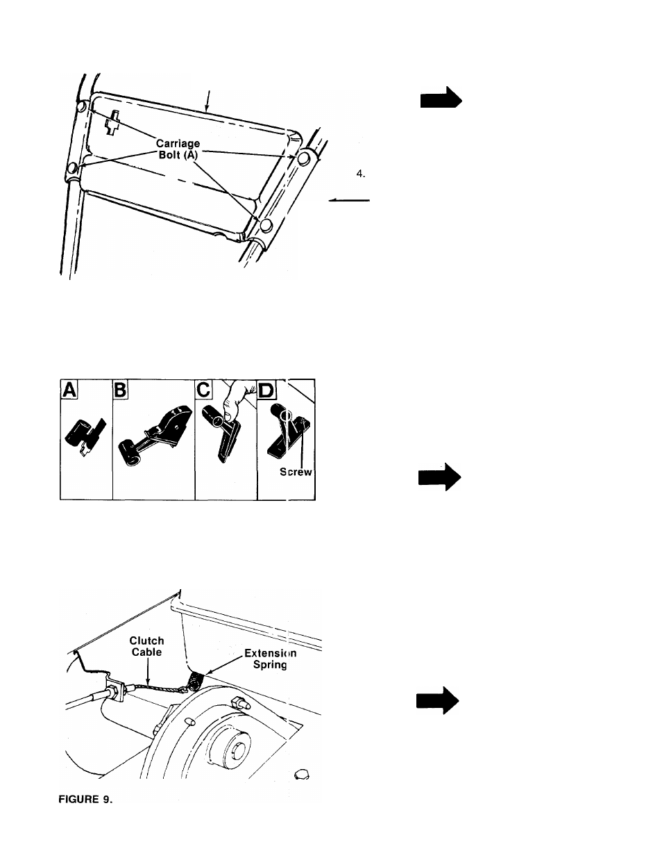
THROTTLE CONTROL INSTALLATION
Assemble the throttle control to the handle panel as
follows.
1. Hold the throttle control assembly beneath the han
dle panel. Turn the control sideways and insert the
lever up through the wide portion of the slot on the
------ handle panel. See figure 8A.
2. After the end of the lever is through the slot, turn
and then tip the control forward as shown in figure
8B to slide it through the slot.
3.
4.
NOTE
The lever must be all the way to the
back
of
the
control
housing
as
shown in figure 8B.
Push the control back into the slot in the handle
panel and press in place. Be certain the control is
locked securely into the slot. See figure 8C.
Secure the throttle control to the handle panel us
ing self-tapping screw (K). See figure 8D.
ATTACHING CLUTCH CABLE
1. Hook the end of clutch cable (already attached to
tiller) over the extension spring as shown in figure
-------9.
NOTE
If spring has come loose, it must be
reassembled to the weld pin on the
idler bracket.