Note, Attaching the drive control cables – MTD 216-406-000 User Manual
Page 7
Attention! The text in this document has been recognized automatically. To view the original document, you can use the "Original mode".
Hole in
2
.
3.
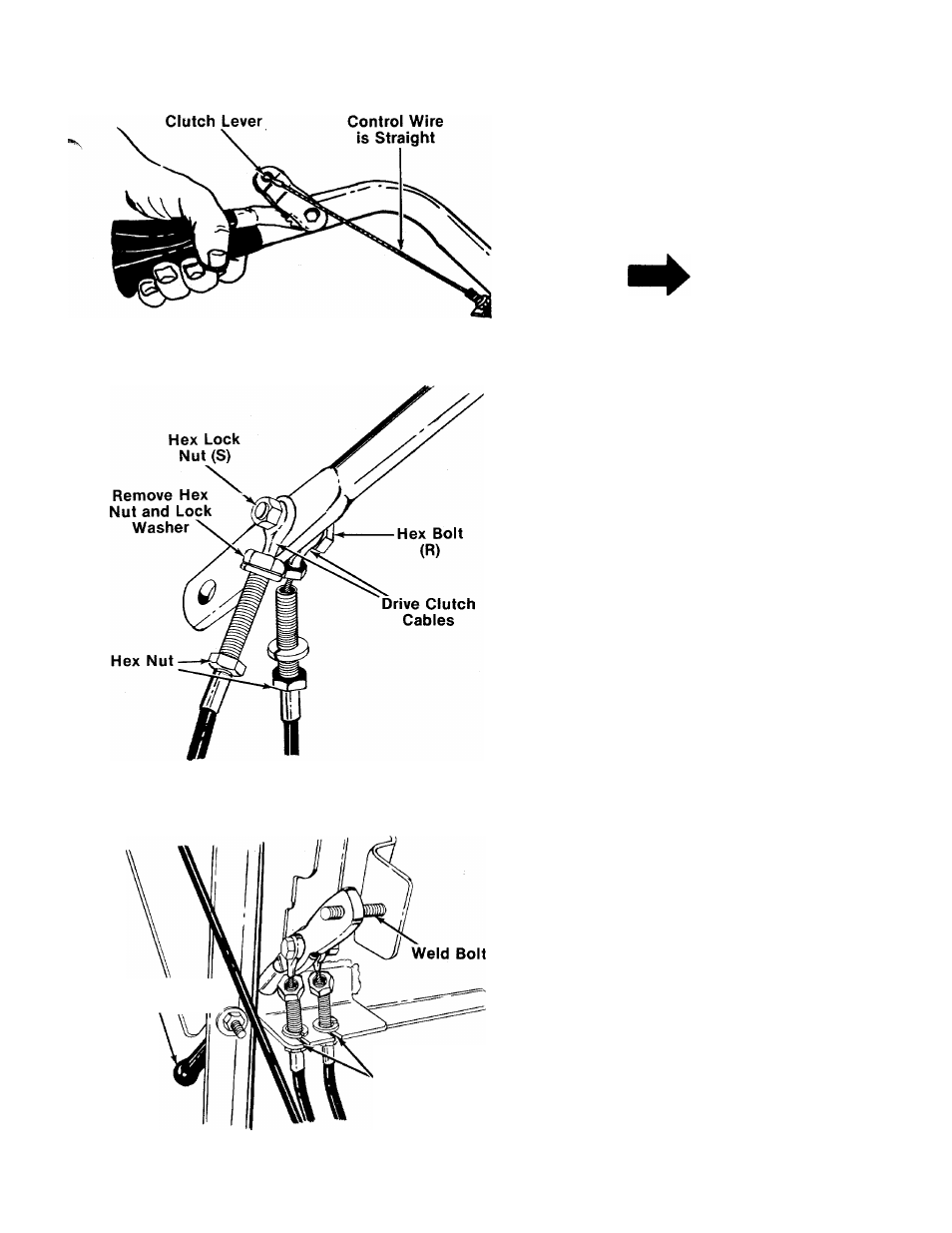
FIGURE 10.
Hook the “Z” end of tine clutch cable into the hole
in tine clutch lever.
With the clutch lever released (in the “up” posi
tion), adjust the bottom nut at the cable bracket so
there is only a slight amount of slack in the control
wire. Tighten the upper nut against the bracket.
Squeeze the clutch lever against the handle. The
■control wire should now be straight. See figure 10.
NOTE
Do not overtighten control wire.
Too much tension may cause it to
break.
ATTACHING THE DRIVE CONTROL CABLES
1. The drive clutch cables are already attached to the
unit. Attach the other end of cables to the upper
hole of drive clutch lever (W), one on each side,
using hex bolt (R) and hex lock nut (S). See figure
11
.
2
.
Remove one nut and the lock washer from the end
of each drive clutch cable. Thread the other hex
nut all the way down the cable as far as it will go
as shown in figure 11.
FIGURE 11.
Gripped End of
Clutch Lever
Slots on
Cable Bracket
3.
4.
5.
Push the gripped end of drive clutch lever through
the slot in the handle panel.
Slip the wire on the cables through the slots in the
cable brackets as shown in figure 12. Push the
ends of the cable up through the holes in the
bracket. Rethread hex nuts and lock washers on
the end of the cables. Do tighten at this time.
Place end of drive clutch lever over weld bolt on
handle panel. See figure 12.
FIGURE 12.