Using your rotary mower, Adjustments, Cutting height adjustments – MTD 112-060A User Manual
Page 7: Handle position, Throttle control wire, Screw on â \ engine m, Warning
Attention! The text in this document has been recognized automatically. To view the original document, you can use the "Original mode".
USING YOUR ROTARY MOWER
«V For the best results, do not cut wet grass because
it tends to stick to the underside of the mower,
preventing proper discharge of grass clippings. If
wet grass must be cut, reduce walking speed to
help distribute the clippings more effectively.
New grass, thick grass or wet grass may require a
narrower cut. Blade speed should be adjusted to
the condition of the lawn.
The best mowing pattern is one that allows the
clippings to discharge towards the uncut part of
the lawn. This permits recutting of the clippings
to
further
pulverize
them.
When
cutting
high
weeds, discharge towards cut portion then recut
at right angles to first direction.
For best results, cut off one-third or less of the
total length of the grass. Lawn should be cut in
the fall as long as there is growth.
ADJUSTMENTS
A
CAUTION
Do not at any time make any adjust
ment to lawn mower without first
stopping engine and disconnecting
spark plug wire.
CUTTING HEIGHT ADJUSTMENTS
Adjustment may be made by removing and moving
axle bolts to desired position. Cutting heights will
be raised as axle bolts are moved to a lower hole
and lowered as axle bolts are moved to a higher
hole in the deck. All axle bolts must be mounted in
the
same
relative
position.
Belleville
washers
must be assembled on the inside and outside of
the deck so that the cupped side of the washers
are
against
the
deck.
The
spacers
must
be
assembled
between
the
rear
wheels
and
the
belleville washers.
HANDLE POSITION
The upper handle can be adjusted to a high or low
position. The adjustment is made by removing the
hex nuts, lock washers and curved carriage bolts,
and reassembling in the other position. See figure
9.
Low Position
High Position
FIGURE 9.
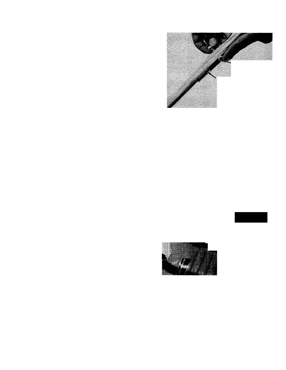
THROTTLE
If
adjustment
becomes
necessary,
the
throttle
control wire assembly can be reset as follows:
1.
Loosen, but do not remove, screw securing
throttle control wire assembly at engine. See
figure 10.
2. Move throttle control lever on handle to
“FAST” position.
Move lever, to which control wire is fastened
at engine, to full open position and retighten
screw
to
secure
throttle
control
wire
assembly.
3.
4
Throttle
Control Wire
Screw On â \
Engine m \
FIGURE 10.
CARBURETOR ADJUSTMENTS
WARNING
If any adjustments are made to the
engine while the engine is running
(e.g.
carburetor),
disengage
all
clutches and blades. Keep clear of
all moving parts and be careful of
heated surfaces and muffler.